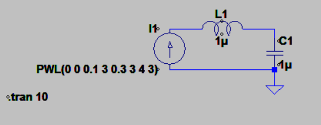
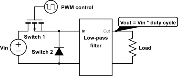
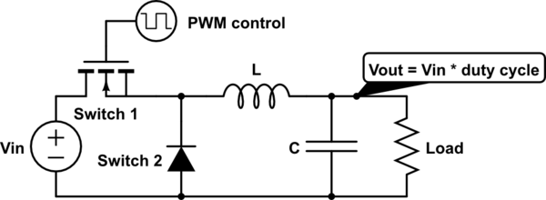
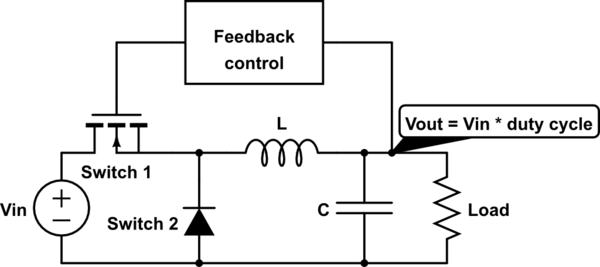
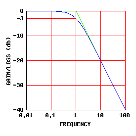
An inductor is a device which adjusts its voltage to keep the same current flowing through. However, the current exponentially decays when there is no source any more. Similarly, a capacitor is a device which keeps the voltage across itself constant. However when charged, the voltage exponentially decays when a load is connected. THe building block of a buck convertor seems to be the L and C. However I am having a hard time understading how an LC circuit actually operates(in a buck). I understand that the capacitor is kind of a snubber capacitor to allow current to flow through and provide a path when the high side PMOS is turned on. However, that job could as well have been done by an resistor, given that Voltage mode control is being used. The only advantage I see to using a capacitor is the efficiency, since energy is not wasted. I applied a current step to my inductor in LTSPICE and this is what I got:
I understand that initially, the voltage at the left hand side of the inductor should actually try to become 0 to allow no current to pass(the initial state). However this doesnt seem to be the case. Can someone explain intuitvely what exactly is going on in the LC circuit. How should it be analyzed?


