2
\$\begingroup\$

I am looking for a way to control an analog signal from another system that changes between 0-1 V.

The user could define the maximum voltage value, for example 0.793 V (the analog signal has resolution of 3 mV). If the input of the analog signal is above the user requirements, I need to open the other control circuit (my boss told me using a relay is safer).

I have two options in my head: the first - sample the analog signal with A2D, and in the uC program compare it to the required user value, but I'm afraid about the safety aspect (the software might crash).

Second - create an analog signal from D2A and compare it to the input signal, but again I depend on the software.

Which option is safer? Maybe another solution?

One of the capabilities of this system is to perform a scan of the eye and display a three-dimensional retinal image. The problem is that the scan is done using an external laser device, which outputs its scanning power in volts from some possible analog wire to sample it. The range is defined by us, the standard set by us, and according to the professional standard.

The maximum output in any case is between 0-1 V. If we sample a voltage that is above the desired value (the value is not yet in our hands and it is a lot of trial and error) then the card will close the device and the laser in less than 25 ms so that the patient's eye will not be damaged. My manager's recommendation is to use a relay to close the voltage and it is also safer, something that is mechanical and ensures full galvanic isolation. There should also be real-time samples of the voltages so that the engineer in the field can set the value to a certain threshold (it varies in each system) and then close the card and the box and that's it.

\$\endgroup\$
11
  • 3
    \$\begingroup\$ Anything wrong with a comparator and reference voltage where the reference voltage is an output from a potentiometer? \$\endgroup\$
    – Andy aka
    Commented Aug 25, 2022 at 14:40
  • 1
    \$\begingroup\$ Even if you were a senior engineer, in any sane organization it would be perfectly acceptable, if not expected, for you to come up with two or three alternative approaches and discuss them with one or more colleagues (or your boss, if the company is small enough that there are no other colleagues). \$\endgroup\$
    – TimWescott
    Commented Aug 25, 2022 at 14:43
  • 1
    \$\begingroup\$ Solutions using software in safety-critical systems certainly do require a lot more certification, which can make them more expensive and inflexible. Please can you edit your question and explain in more detail what the application is and what standards and safety requirements must be met. Without a clear question, a reliable answer can't be written. Thanks. \$\endgroup\$
    – TonyM
    Commented Aug 25, 2022 at 14:45
  • 1
    \$\begingroup\$ There's safety and there's safety. Any "safety" system that leaves it to the user to decide a threshold is only going to be as safe as the user is. You don't leave circuit breaker sizing to management -- it's done by certified electricians. So it sounds like there's an inherent safety issue baked into the product definition, at this point. \$\endgroup\$
    – TimWescott
    Commented Aug 25, 2022 at 14:45
  • 2
    \$\begingroup\$ By the way safety is a whole-system concern. Kuba posted a circuit with a lot of redundancy, but like I said before, random people on the Internet aren't qualified to tell you how much redundancy your product needs or doesn't need. Maybe using software is actually okay for your product - who am I to know? Probably if I was in your position I would design some circuits (one with ADC, one with a comparator, ...) but I would tell the manager I wasn't comfortable evaluating the product's safety requirements and someone properly qualified and experienced should decide which circuit to use. \$\endgroup\$ Commented Aug 25, 2022 at 19:47

1 Answer 1

3
\$\begingroup\$

If you already have the microcontroller, then a PWM output with an R-C lowpass filter will be more than suitable as a reference voltage source.

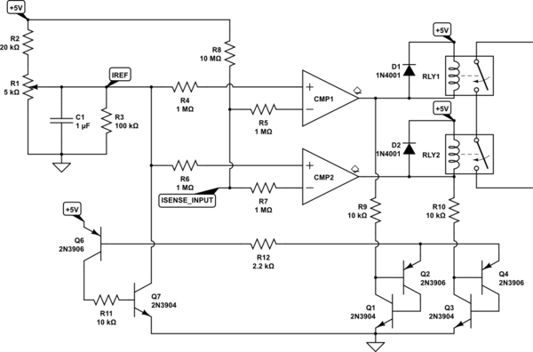
But a simple potentiometer and a comparator - or two comparators for redundancy - would be just as suitable. The enclosure of the device would have a threaded hole through which the technician can adjust the potentiometer. Once the adjustment is done, a screw goes into the hole and closes it. Two such holes can be provided - the other one can have a pad or a turret terminal underneath, so the technician could insert a multimeter probe and measure the voltage (relative to enclosure ground).

With suitable reed relays, the reaction time to overcurrent should be 1ms or less. 25ms is "forever".

A general design approach to such a circuit would be fail-safe behavior: any one component can fail, in any imaginable failure mode, and the overcurrent protection is not lost.

schematic

simulate this circuit – Schematic created using CircuitLab

The analysis below is only meant as an educational example. Consult a professional engineer with relevant experience to design anything going into a product.

A simplistic look at failure modes:

  1. R1,R2 open -> IREF=0V -> fail safe, load off
  2. R1,R2 short - unlikely
  3. R3 open -> small change of IREF
  4. CMP1 or CMP2 inputs fail shorted to 0V or VCC -> small change of IREF, the other channel maintains protection
  5. D1 or D2 shorts or opens: comparator output overstressed and fails -> other channel maintains protection
  6. RLY1 or RLY2 shorts -> other channel maintains protection
  7. RLY1 or RLY2 opens -> fail-safe, load off
  8. R4-R7 short -> no consequence
  9. R4-R7 open -> channel behavior arbitrary, other channel maintains protection
  10. I_SENSE_INPUT open: R8 pulls up the inputs, causing both channels to trip (thanks to pstechpaul)
  11. Q1-Q2 and Q3-Q4 form SCRs that latch the fault condition and drop the reference current to 0, causing relays to open (thanks to pstechpaul)
  12. Failures of Q6, R11, Q7, Q1-Q4, etc. are fail-safe or only remove functionality. The failure mode analysis of those is left as an exercise to the reader.

As pstechpaul has mentioned, this circuit would also need means for self-test and calibration check.

\$\endgroup\$
4
  • 1
    \$\begingroup\$ Some refinements to your circuit might be: (1) 10 Meg pull-ups on the inverting inputs to deal with open circuit input failure, (2) fault simulator switch(es) to test operation, and (3) a calibration input with GO/NOGO thresholds injected into the I_SENSE input, and (4) a latching or E-stop circuit that requires a manual reset upon fault detection. \$\endgroup\$
    – PStechPaul
    Commented Aug 25, 2022 at 19:34
  • 1
    \$\begingroup\$ @PStechPaul All excellent ideas, by the way. To the OP: you see, the devil is in the details, and such designs have to undergo reviews with multiple people with relevant experience. If you think this is complex, you have no idea what faces you to implement the same functionality using a microcontroller. \$\endgroup\$ Commented Aug 26, 2022 at 0:36
  • \$\begingroup\$ This is amazing, but how can I check the fail safe? This is function that I need \$\endgroup\$
    – Knowledge
    Commented Aug 26, 2022 at 17:06
  • \$\begingroup\$ @Kubahasn'tforgottenMonica could you explain to me how the circuit works? in the start condition, the CMP output will be 0v which means the relay will work and it doesn't good, what are the input voltages for the CMP? I mean what are the values that comparators can drive? \$\endgroup\$
    – Knowledge
    Commented Aug 28, 2022 at 6:08

Your Answer

By clicking “Post Your Answer”, you agree to our terms of service and acknowledge you have read our privacy policy.

Not the answer you're looking for? Browse other questions tagged or ask your own question.