-2
\$\begingroup\$

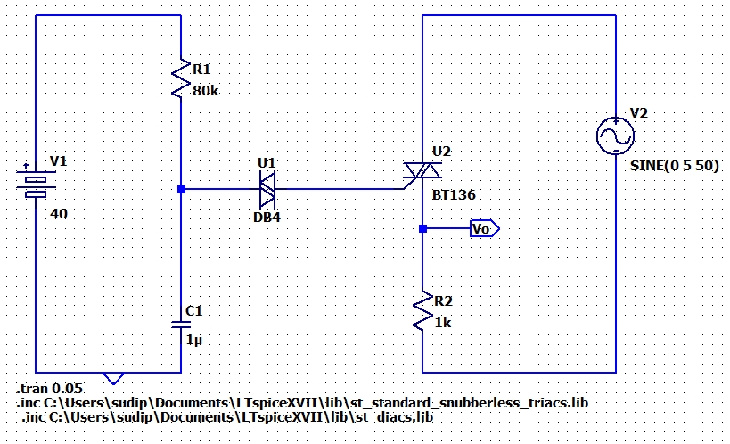
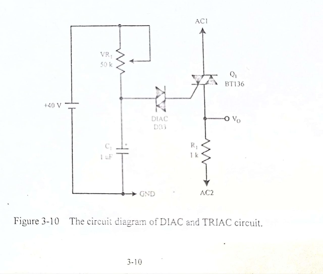
I was given to simulate the circuit in the lab. The picture of the circuit from the manual is given below. Diagram from the manual.
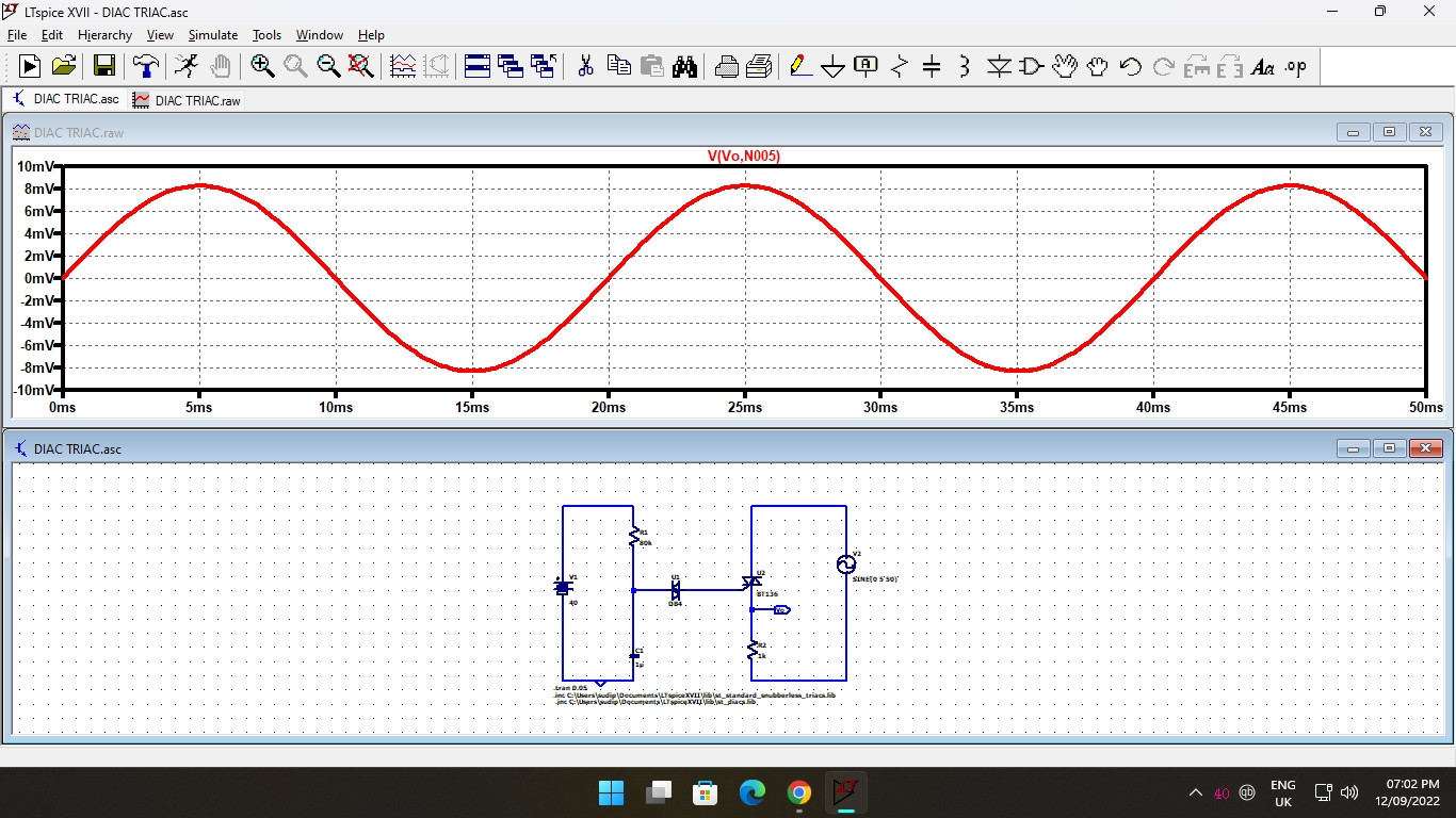
I made the same circuit in LTspice. Implementation in LTspice

The problem is that I do not get the expected output as you can see here. Output I was supposed to get a chopped-off sine waveform. Instead, I get this sine waveform which is in the mV range(peak to peak). What am I doing wrong here? Please help me.
\$\endgroup\$
8
  • 3
    \$\begingroup\$ There is always zero gate current into U2 in your circuit. \$\endgroup\$
    – Andy aka
    Commented Sep 12, 2022 at 13:18
  • \$\begingroup\$ How to solve this issue? The given manual doesn't specify this. Also, the course tutor started the lab before teaching the theories. Please, help. \$\endgroup\$
    – Rajiv Das
    Commented Sep 12, 2022 at 13:43
  • 4
    \$\begingroup\$ As drawn, zero current can flow into the gate. Hint: V1 and V2 are completely isolated in LTspice - but is this the case in reality? \$\endgroup\$
    – rdtsc
    Commented Sep 12, 2022 at 13:52
  • 4
    \$\begingroup\$ Current needs a circuit to flow through. \$\endgroup\$
    – Andy aka
    Commented Sep 12, 2022 at 13:52
  • 1
    \$\begingroup\$ The circuit from the manual is not working, so your simulation is correct. \$\endgroup\$
    – Jens
    Commented Sep 12, 2022 at 19:25

1 Answer 1

0
\$\begingroup\$

Generally, diac is supplied with main voltage.

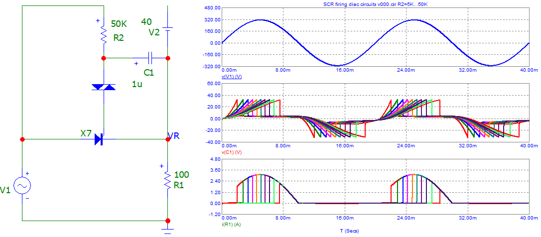
Here an example of "firing" an SCR with such topology (Diac, R-C).

enter image description here

With a battery, it would be a "little" different, if wired correctly ...
Note also that a minimum value resistor is needed ... for safety of devices.

\$\endgroup\$

Your Answer

By clicking “Post Your Answer”, you agree to our terms of service and acknowledge you have read our privacy policy.

Not the answer you're looking for? Browse other questions tagged or ask your own question.