I built a 3.3/5/12/25V power supply from a Macintosh G4 API1PC36 power supply using Daniel Haertle's project description. I placed a switch between the PwrOn line and GND and a LED between 5V and GND. I used a \$27\Omega\$, 10W wire wound resistor from the 3.3V/sense line to GND so the power supply does not go into standby mode and I wired 3.3V, 5V, 12V and 25V lines to banana plug ports mounted on the body of the power supply. To try to ensure the wires can handle the power used, the 3.3V, 5V and 12V lines are triple wires. See Figure 1. 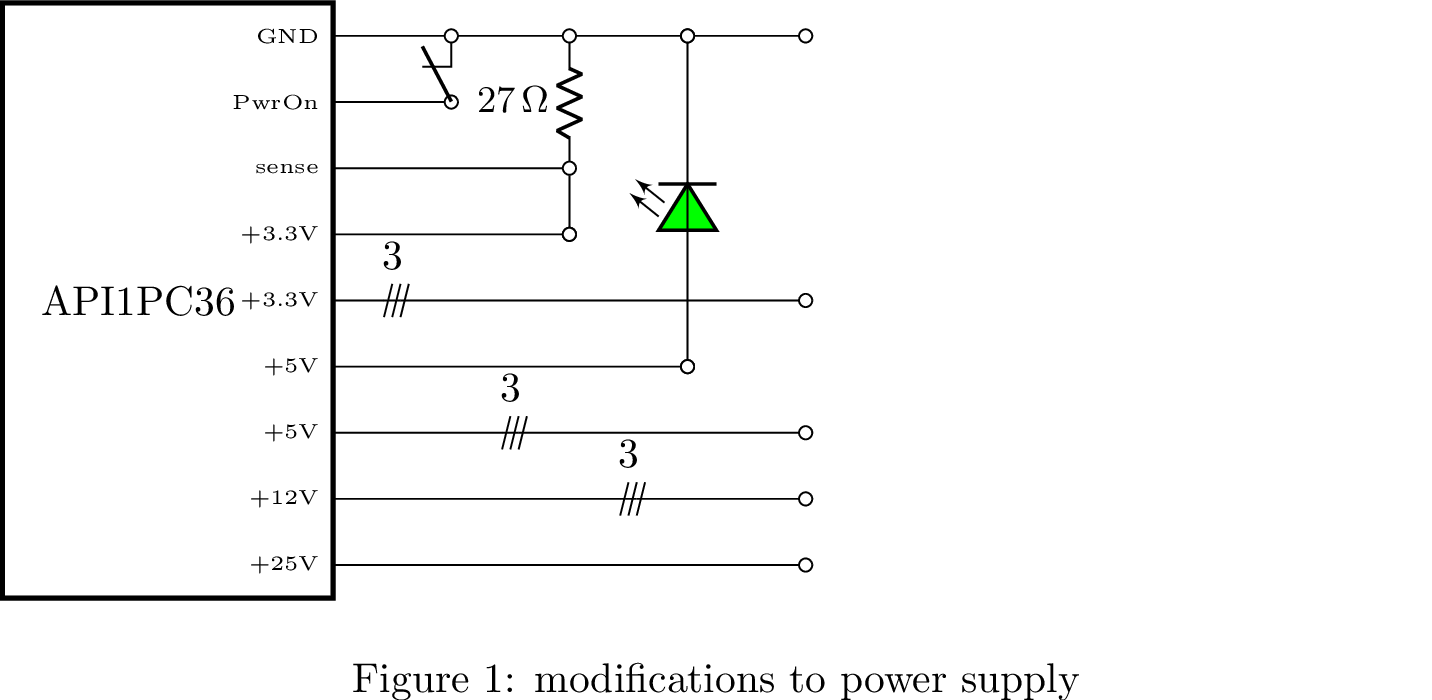
I want to use the power supply to power a 12V 100W halogen microscope light with a PWM dimmer between the two to control the luminosity. The power supply works fine with the halogen lamp directly connected to the 12V line, see Figure 2. 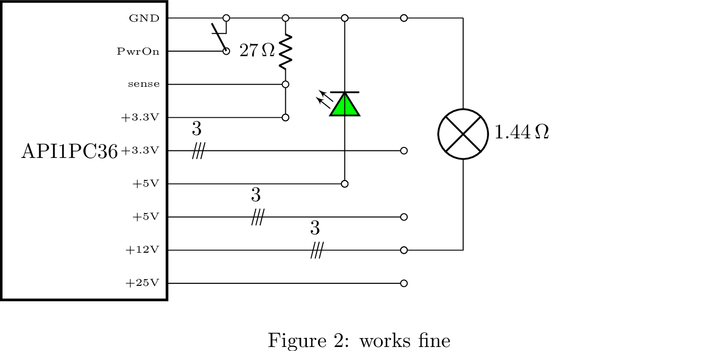
With the PWM between the power supply and the lamp, the power supply switches itself off if started with the PWM set to anything less than about 90%. It does not switch off if started with the PWM set high, but does switch off when I start to turn the PWM down, see Figure 3.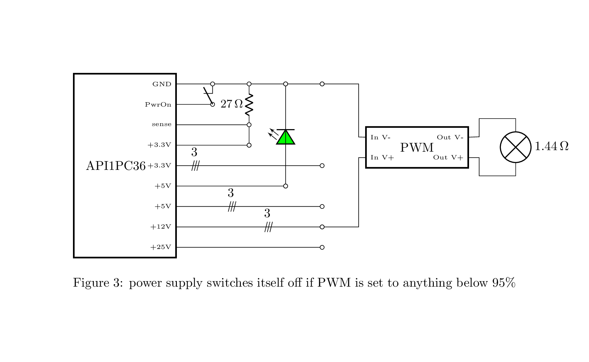
If I put a \$1.2\Omega\$ incandescent lamp on the 3.3V line then the 12V line is fine with the PWM dimmer through the PWM's full range. See Figure 4.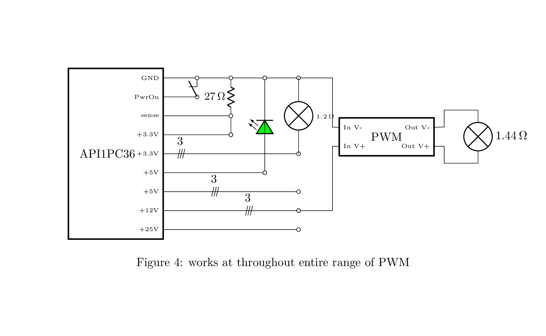
If I put a \$30\Omega\$ resistor on the 3.3V line then the PWM dimmer only works over the top 3/4 of its range, but power supply shuts itself down when the PWM is in the bottom quarter of its range. See Figure 5.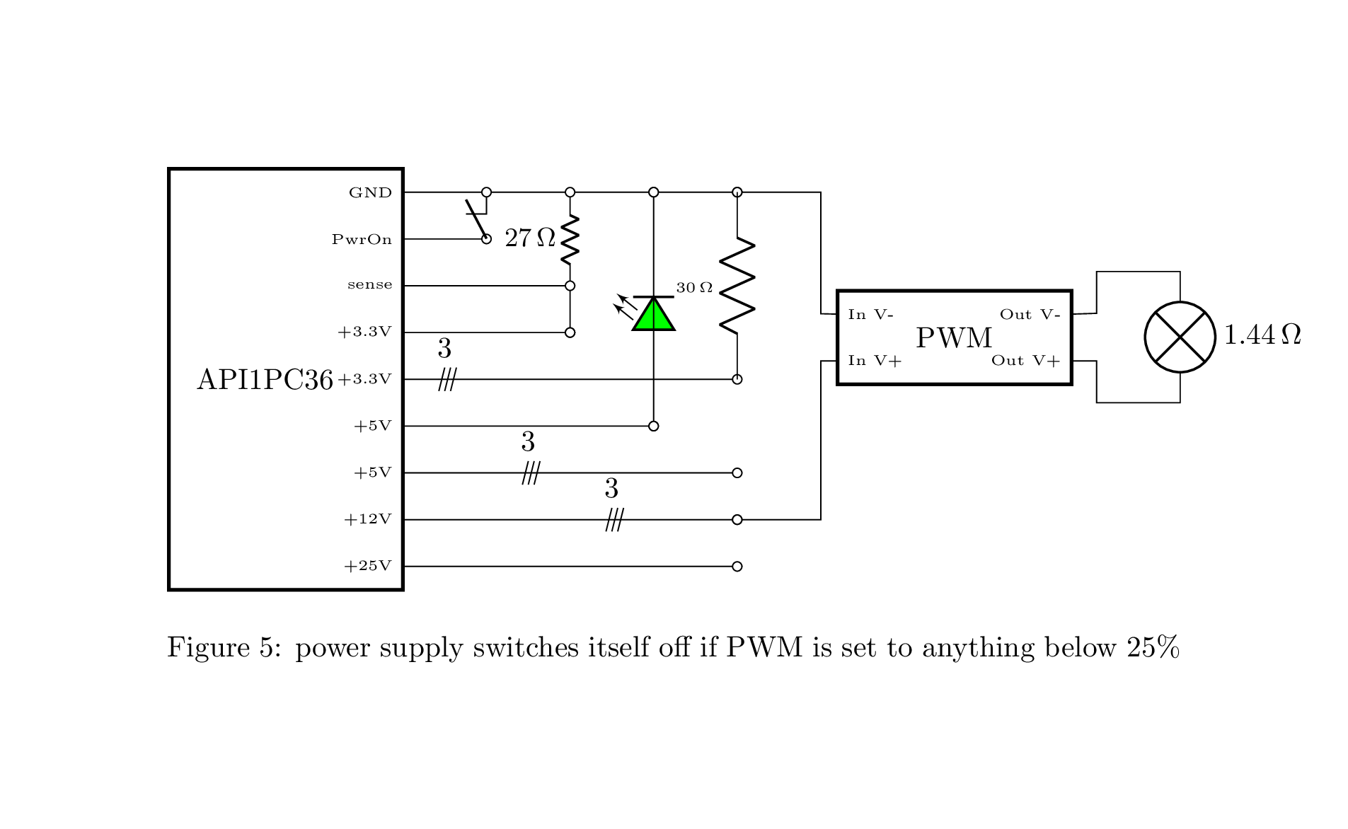
I have previously built a similar power supply for a 12V 100W halogen microscope lamp from a Seasonic SS-300TFX PC power supply which works fine with the PWM and a 12V 100W lamp. In that case, following DroneBot Workshop's instructions I put a \$18\Omega\$ wire wound resistor on the 5V line as the constant load to prevent the ATX going into standby mode. On the API1PC36, I did try putting the \$1.2\Omega\$ lamp on the 5V line as a load but this behaved basically the same as Figure 3.
- What is causing this behaviour? Is it something related to the frequency of the PWM experienced by this Arduino user??
- What further data can I gather to diagnose the problem?
- Do I need to change the resistance I put on the 3.3V/sense line to a lower value? I would like to keep the power consumed by the 3.3V/sense line as low as possible.
- Is there better solution than changing the resistance of the 3.3V/sense line? Is there a circuit I could put between the power and supply and the PWM to make them work more smoothly together? What would the appropriate circuit design be?

