Jump to TLDR below for a shorter answer:
The Arduino Uno Rev2's 3.3v line is powered from the FT232R usb to serial chip's 3v3 internal regulator. Max draw on this is under 50mA. Pretty pathetic actually, which is why there was a move to a dedicated regulator in the Rev3.
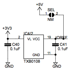
The Wifi Board does not connect to the 3v3 pin. Normally, it is powered by 5v, has it's own 3v3 regulator, and uses a TI TXB0108 Level Translation chip. It takes two arbitrary (with a certain range) voltages, and allows level translation to communicate between the two. The main chip on the Wifi Board is a 3v3 device. So are SD Cards.
So here is the problem. Sloppy, idiotic, inconsistant notation by Arduino.
The Arduino Rev3 does not add the IORef pin listed on the Official Schematic.
As noted online, in adding the IORef, they said that it's for future expansion. 5v Boards, like the default Arduino UNO or AVR based ones, ioref is tied to 5v. For the newer 32bit Due runs at 3.3v. It's IORef is tied to 3.3v.
Revision 3 of the board has the following new features:
1.0 pinout: added SDA and SCL pins that are near to the AREF pin and two other new pins placed near to the RESET pin, the IOREF that allow the shields to adapt to the voltage provided from the board. In future, shields will be compatible both with the board that use the AVR, which operate with 5V and with the Arduino Due that operate with 3.3V.
The Wifi Board's schematic shows that the IORef pin goes to the TXB0108's Pin 19, VccB (The side that communicates with the Arduino. VccA is for the wifi chip). It also shows... that the jumper is tied to 5v.

Now, why would they tell you to jump ioref to 3.3v, or use the jumper, when the UNO rev2 and rev1 are 5v IO devices? Or when the jumper ties ioref to 5v, and they know that will cause problems? Go fig. There really shouldn't be a reason. Everything on that board is supposed to be powered and externally communicated at 5v, so unless you have a 3.3v modified board or Due or something, you shouldn't. A REV2 board will with ioref tied to 3.3v will power half of the TXB0108 and a cap, along with your TMP102 and it's pull up resistors
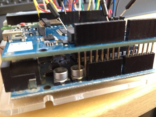
But there is still a problem. The Arduino, the TXB0108, and the TMP102, even at full current draw, should still be less than 50mA from the FTD232R. The TXB0108 and the TMP102 are both under 1mA at while fully active. Something is causing the 3v3 line to go down low. It could be that the Wifi boards schematic isn't correct either, the ioref could be tied to something else as well. Maybe a bad board. Or you have a short that's causing it to go down. Maybe the capacitor on the rev2 board, near the power header where ioref would be, is shorting out against the wifi boards ioref pin. Since you have 3.3v jumpered to it, your essentially shorting out or tainting the 3.3v line.

TLDR;
First, check the 3v3 line when jumpered. It should not be less than 3.3v while everything is on. Make sure you have no shorts and nothing else (except the wifi board and tmp102 board) connected. (anything more would require a logic analyzer or oscilloscope, to see if there is corruption on the i2c data lines.)
Also, make sure that the ioref pin is not sorting out on the capacitor underneath it.
Then, due to the information above, if (and at this point that's a big IF, I don't trust Arduino Documentation) the ioref is on the board according to the schematic, just connect it to 5v, either through the jumper on bottom, or using a wire from the 5v to the ioref header. Given the level translation chip, that's how it is intended to work, and it should work.


