2
\$\begingroup\$

I learned that "Current always flows from high voltage to low voltage". And that is the reason why current flows in the direction of a circuit, as shown in the image below.

enter image description here

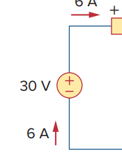
However, when I look closer at the voltage source, the textbook says the current flows like this, below. enter image description here

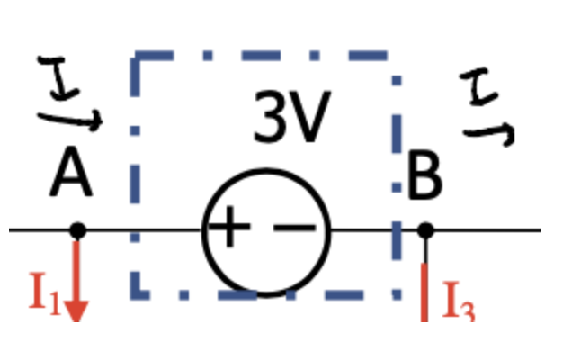
Moreover, in the example below, the textbook says I have to calculate Vab = Va-Vb=3V. It means the current flows from B to A, which is different from the above statement that the current flows from + to - of a voltage source.

enter image description here

I am confused about the direction of the current flow because it seems like it's all different from different contexts.

\$\endgroup\$
2
  • 1
    \$\begingroup\$ The two bottom examples does not show the full picture. Current only flows in loops so there must be something on the outside if you zoom out. \$\endgroup\$
    – winny
    Commented Oct 21, 2022 at 12:12
  • \$\begingroup\$ This is a glib statement that only creates confusion. \$\endgroup\$
    – Chu
    Commented Oct 21, 2022 at 22:56

4 Answers 4

4
\$\begingroup\$

You have to tell apart sources of voltage or current from loads.

The usual way to put it is the passive sign convention. With that convention voltage and current are the same direction in loads, and opposite direction in sources. So their product is positive in loads and negative in sources. So loads have positive power and sources have negative power. That's why it's called passive, because a positive sign means a device takes power from the electrical circuit.

\$\endgroup\$
3
\$\begingroup\$

There is a difference in polarities when you consider sources and load components (like resistors,etc).

  1. For Sources, since they "give out" power in the form of a potential difference V and current I, the 'emitting end' of the source will be positive and the 'terminating end' will be negative. Generally for DC sources, + and - signs are given for positive and negative terminals to give you an idea about how that source is giving out its power in the circuit.

  2. For loads, it is a different story. They 'absorb'/'receive' power, so they cannot be assumed with the same notations as we did with the source. So, the end from which the current enters into the load will be denoted with + sign and the end from which the current leaves is denoted with - sign. It's nothing wrong if you think about it. Inside the load, the current still goes from + end to the - end. It just wasn't visible to you in the circuit diagram, that's all.

The reason why the source and load have different notations is simple : One gives out electrical energy to the circuit and the other receives it. They cannot have the same notation because it makes the entire loop equations incorrect if we take all the element types as same.

  1. In the last picture, the Va-Vb = 3V holds a different meaning than what you are assuming. If Va-Vb > 0 , it means that A has more electric potential than B. As you mentioned in your question, "Current flows from higher potential to lower potential" , it will be true here. But, the direction of I in the picture (written in the black sketch) is wrong. It will go from the + end to the rest of the circuit, not directly to the - end.

Something like this :

enter image description here

PS: I tried give an intuitive suggestion on how to understand the directions, which is why I might have oversimplified the definitions of various things in my answer. Kindly ignore mistakes regarding unclear definitions.

\$\endgroup\$
3
\$\begingroup\$

Some things absorb energy, and some things emit energy.

Batteries and other voltage sources can donate energy to the rest of the circuit, but most components, like the resistor in your examples, cannot.

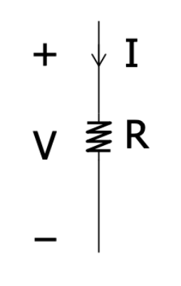
When current flows through a device in the direction where it enters the high potential terminal, flows through the device to exit at the low potential end, then the device is absorbing, or receiving energy. LEDs and resistors and most things, really, do this; they absorb energy and convert it to some other form such as light or heat or motion.

You pointed out that the voltage source or battery does the exact opposite, with current flowing through the device from its low potential end to high. This makes sense, because those devices are donating energy to the the other components in the circuit. This must be true, because of the law of conservation of energy. If light and heat and kinetic energy is leaving a circuit (because of resistors and LEDs and motors and wotnot), something must be providing that energy, the battery in this case.

More interesting is the fact that if somehow you managed to get current in a battery to flow through it in the direction high potential to low (just like a resistor), then the battery must be receiving energy, not donating. In fact this is exactly what we do to charge a battery. Unlike a resistor, a battery is designed to store that energy chemically (instead of waste it as heat) for recovery later.

By contrast it's impossible to get current to flow in a resistor in any other direction than high to low potential; the voltage across the resistor will always be highest where current enters, that's Ohm's law. It's because resistors cannot possibly do anything other than convert electrical energy to heat, never the other way around. Resistors can't ever donate energy to other parts of the circuit, they can only receive energy and convert it to heat (also see my note about this at the end).

A capacitor, on the other hand, is quite capable of both receiving and donating energy. Current flowing through it will always cause potential at the terminal where current enters to rise with respect to the terminal where current leaves. If this results in the potential difference increasing, then the capacitor is charging, and storing more and more energy. If the voltage across the capacitor is reducing, then it's discharging and donating energy.

A capacitor's stored energy can be recovered by allowing its potential difference to push current through some external energy recipient. In such a case, with the capacitor now discharging, donating energy, that current must be in the direction in which it exits via the capacitor's higher potential terminal, just like a battery.

Note: Actually, it is possible for a resistor to donate energy to other parts of a circuit, in the form of noise current. Heat in a resistor causes a small amount of AC current to flow, but that's another topic altogether.
\$\endgroup\$
-1
\$\begingroup\$

It may be unnecessary to think about actual direction of current flow at the beginning. Current usually flows from a node with higher potential to node with lower potential. . Common sense tells that current should originate from a voltage source but shouldn't flow into it.Sometimes you may see that current flows into a voltage source source. This happens if that potential has lesser value than some other node from which current is flowing. Assume a particular direction of current flow, write circuit equations in all meshes or nodes. If you get a negative value of current, then conclude that current was flowing in the opposite direction in that branch. You can learn about these things in Mesh and Nodal analysis which you can refer in a circuit analysis book.

When writing circuit equations, use a sign convention such as - to + is negative and + to - is positive when viewing voltage sources. This is called passive sign convention

Edit:

You seem to be asking basic questions. I recommend reading one or more of these books to know answers to such questions.

  1. Engineering circuit analysis, 9e, Hayt, Kemmerly, Durbin, Phillips.
  2. Network analysis, 3e, M.E Van Valkenberg.
  3. Network analysis and synthesis, 2e, Franklin Kuo.
\$\endgroup\$

Your Answer

By clicking “Post Your Answer”, you agree to our terms of service and acknowledge you have read our privacy policy.

Not the answer you're looking for? Browse other questions tagged or ask your own question.