1
\$\begingroup\$

I have been stuck on this problem for a long time. Close to 2.5 months now..... Please someone help a homie out.

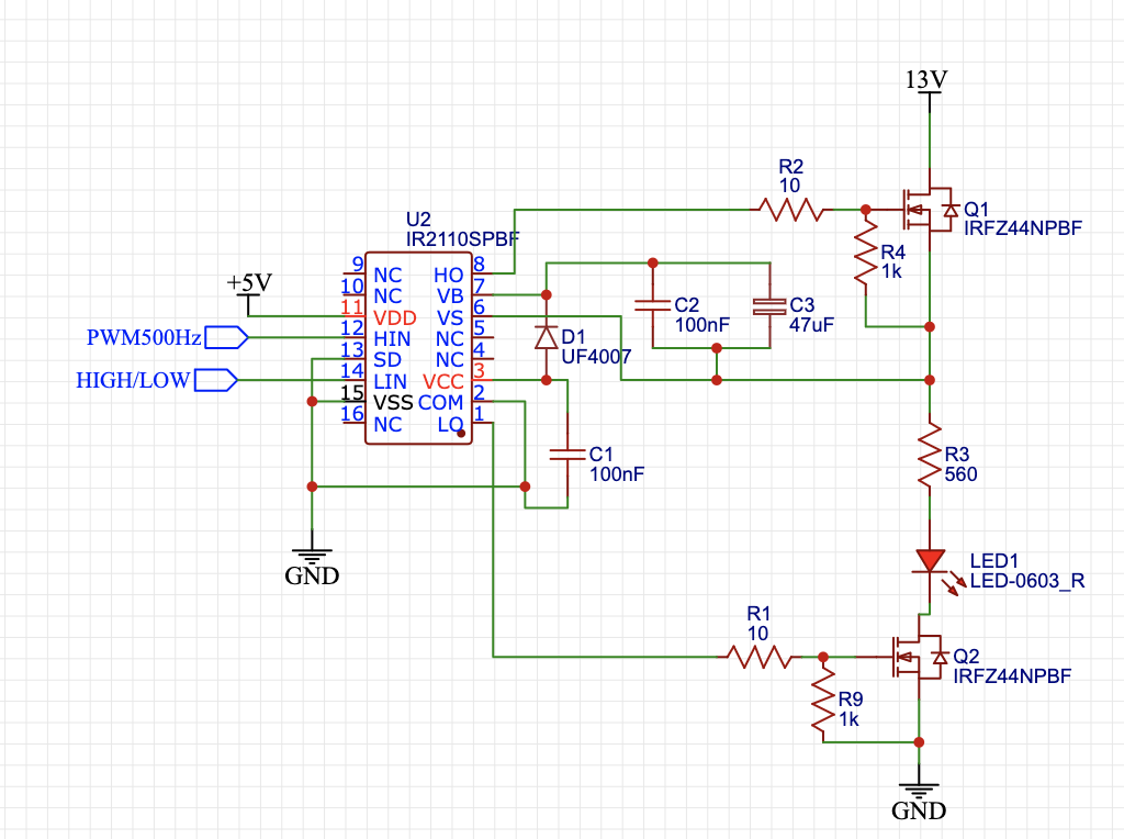
Here is my schematic exactly the way I have it wired (I will eventually use an actual BLDC motor with 3 phases, but I'm just trying to get the circuit to work first using LEDs):

enter image description here

For U2 I apply a 500 Hz PWM signal to HIN and I apply a LOW signal to LIN. For U1 I apply a LOW signal to HIN and I apply a HIGH signal to LIN. When I apply these signals to U2 & U1 it will make Q1, Q4, and Q2 turn on. Because both Q2 & Q1 are on at the same time this causes my a short circuit which damages my IR2110 IC's. I literally bought 50 of these IC's and spent around $100 and i'm down to only about 20 now.

I've tried changing the bootstrap capacitor value & gate resistor value. I've tried running the circuit without pulldown resistors on the MOSFETs. I've tried increasing the pull down resistor values to 10k and 100k. I've tried grounding the upper MOSFET pulldown resistor instead of attaching it to the source. I've tried changing the bootstrap diode. I have no idea what else to even try at this point.

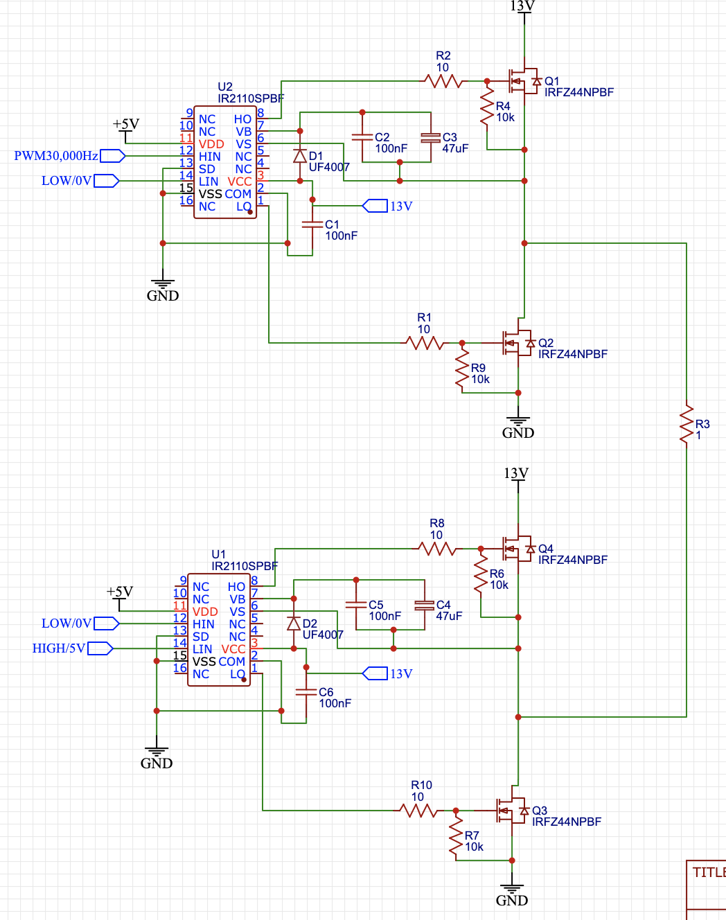
When I run this circuit using only 1 IR2110 with this circuit everything works perfectly:

enter image description here

Anybody have any ideas on what to do? I've tried looking up many guides on the internet, but it seems as if i'm doing the exact same thing that these guides are telling me to do and yet it still doesn't work for me.

Guide 1

Guide 2

Guide 3

Edit

Here is the updated schematic after taking some things into consideration. I changed the resistor values to 10k, switched out LEDs for a 1 ohm resistor which will represent my BLDC motor, switched to a 30k Hz PWM signal instead of 500Hz, and I switched out the HIGH/LOW inputs because they were confusing and I am now showing the exact signals I would be applying for the first phase of the motor. Any other recommendations?

Also Just how important is PCB design when designing a circuit like this? Right now I just have everything on a breadboard using as short as possible wires. Is this potentially the problem i've been having?

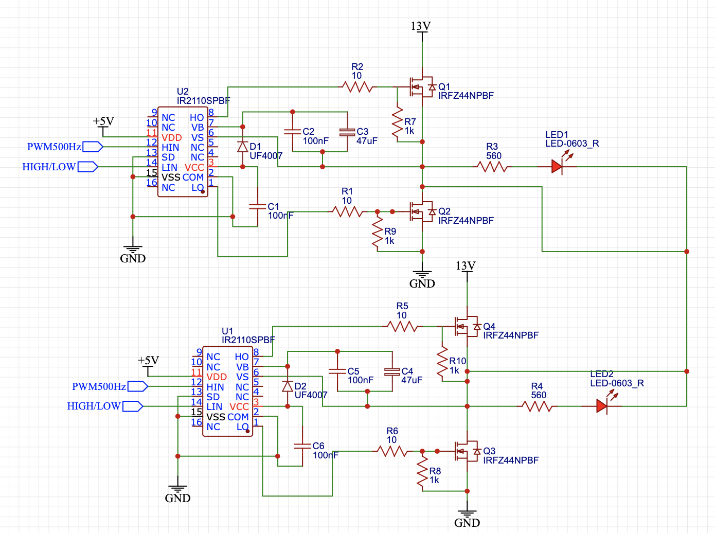
enter image description here

\$\endgroup\$
8
  • \$\begingroup\$ You show the inputs hin and lin as being driven by a PWM signal and a high/low selection signal - that’s not how this chip works. Is this schematic correct in that regard? \$\endgroup\$
    – Bryan
    Commented Nov 9, 2022 at 3:13
  • 5
    \$\begingroup\$ You've short-circuited your LED's, they will never light. \$\endgroup\$
    – Kyle B
    Commented Nov 9, 2022 at 3:41
  • \$\begingroup\$ What makes you think all these ‘guides’ are correct? There’s a lot of incorrect and marginally correct information out there. Have you followed the manufacturer’s recommendations? Pcb layout is very critical as well. \$\endgroup\$
    – Kartman
    Commented Nov 9, 2022 at 5:18
  • \$\begingroup\$ Put a resistive load on the high side that represents the current you expect to be switching. Use an oscilloscope to view the switching performance and your boost voltage. That should give some insight into how the high side is working. \$\endgroup\$
    – Kartman
    Commented Nov 9, 2022 at 5:21
  • 1
    \$\begingroup\$ PCB layout is very important, especially for 30 kHz. But you might get by with a carefully constructed soldered circuit. 10 kHz would be adequate, and less critical. For a simple DC motor you can PWM one side while holding the other side low, but not for three phase BLDC or induction motors. \$\endgroup\$
    – PStechPaul
    Commented Nov 9, 2022 at 18:27

1 Answer 1

2
\$\begingroup\$

Several problems:

Vcc is not connected, and needs to be between 10 and 20 volts.

500 Hz may not be high enough for bootstrap operation.

1k gate to source resistor is too low, and will drain the drive voltage on the high side.

As noted in comments above, LED loads are shorted, and all three outputs are shorted together.

Also as noted, Lin is connected to a HIGH/LOW signal.

Your example with a single half-bridge hes the LED load between MOSFETs, instead of to GND.

Show the actual waveforms of your PWM and H/L signal.

\$\endgroup\$
10
  • \$\begingroup\$ I have updated my schematics with your recommendations. Anything else to consider? The only thing I am still unsure about is you said "Lin is connected to a HIGH/LOW signal". I have updated this to represent exactly what I will be doing in when I try to drive one phase of the motor. Is that what you mean by this? \$\endgroup\$
    – Trev347
    Commented Nov 9, 2022 at 14:46
  • 1
    \$\begingroup\$ @Trev347 the LIN and HIN signals must both be PWM, they must be complementary and it is almost mandatory to have "dead time" - a gap between a high level on HIN and a high level on LIN (and vice versa). If these signals are high at the same time you'll get a branch shoot through: Q1 and Q2 conduct simultaneously and short out your power supply. Dead time is added to the HIN and LIN signals to guarantee that even when the system takes some time to turn off (we're talking nanoseconds here) there's no chance of a branch shoot through. Deadtimes are usually 1 microsecond or less in my experience. \$\endgroup\$
    – Bryan
    Commented Nov 9, 2022 at 17:42
  • \$\begingroup\$ @Bryan why do you need to PWM both LIN and HIN? Is it because you need to charge the bootstrap capacitor? If so, why can’t you just charge the bootstrap capacitor through the lower mosfet on the 2nd IR2110? Current would be able to travel from C2 & C3 through the 1 ohm resistance load and through Q3 to ground correct? \$\endgroup\$
    – Trev347
    Commented Nov 9, 2022 at 21:38
  • 1
    \$\begingroup\$ @Trev347 charging through the load will not guarantee a full charge of the bootstrap as the load voltage will be subtracted. \$\endgroup\$
    – Bryan
    Commented Nov 10, 2022 at 4:01
  • 1
    \$\begingroup\$ For a simple DC motor and an H-bridge, you would turn on the low side MOSFET of one half-bridge, and apply PWM to the other pair. To determine maximum duty cycle, make sure the low side is on long enough to charge the bootstrap capacitor, and it needs enough charge to maintain sufficient gate voltage for the ON time. \$\endgroup\$
    – PStechPaul
    Commented Nov 10, 2022 at 23:34

Your Answer

By clicking “Post Your Answer”, you agree to our terms of service and acknowledge you have read our privacy policy.

Not the answer you're looking for? Browse other questions tagged or ask your own question.