Regarding two-terminal devices in parallel with each other, you have this arrangement, where each impedance (even when the impedances are inductive or capacitive, resistive or any combination thereof) represented by \$Z\$:
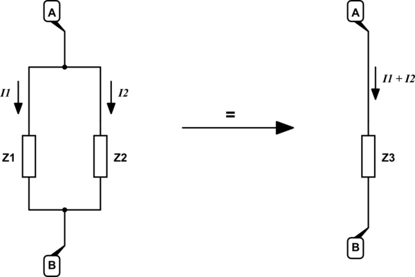
simulate this circuit – Schematic created using CircuitLab
$$
\begin{aligned}
\frac{1}{Z_3} &= \frac{1}{\frac{1}{Z_1} + \frac{1}{Z_2}} \\ \\
Z_3 &= \frac{Z_1 Z_2}{Z_1 + Z_2}
\end{aligned}
$$
Clearly, if either impedance is zero, or in other words is a short circuit across the other, then the combined impedance is also 0Ω, and the pair can be replaced by a simple zero-ohm path:
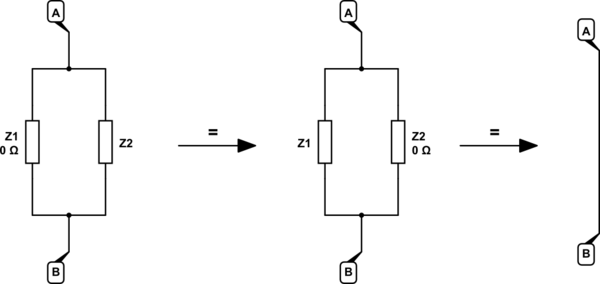
simulate this circuit
This principle applies to any short-circuited two-terminal device, or compound circuit with only two externally accessible terminals:
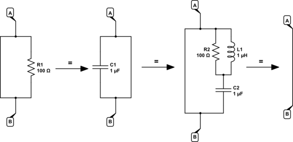
simulate this circuit
Theoretically (and in practice too, if you can somehow produce a true zero-impedance short-circuit), a zero-ohm path can have no voltage across it. If the short circuit impedance is \$Z_1=0\$:
$$
\begin{aligned}
V_{AB} &= I \times Z_1 \\ \\
&= I \times 0 \\ \\
&= 0
\end{aligned}
$$
Since both parallel elements (the short-circuit \$Z_1=0\$ and the element being shorted \$Z_2 \ne 0\$) have the same voltage across them, there can be no current passing through the non-zero impedance \$Z_2\$, by Ohm's law:
$$
\begin{aligned}
I_2 &= \frac{V_{AB}}{Z_2} \\ \\
&= \frac{0}{Z_2} \\ \\
&= 0
\end{aligned}
$$
Therefore the element being shorted circuited has:
- No voltage across it
- No current through it (all current passes via the short circuit)
Consequently, any application of Kirchhoff's voltage or current laws to that shorted device will yield a zero term, and disappear from the algebra entirely. In other words, the element can be removed completely (leaving just the short-circuit path) without affecting the state or behaviour of the entire circuit at all.
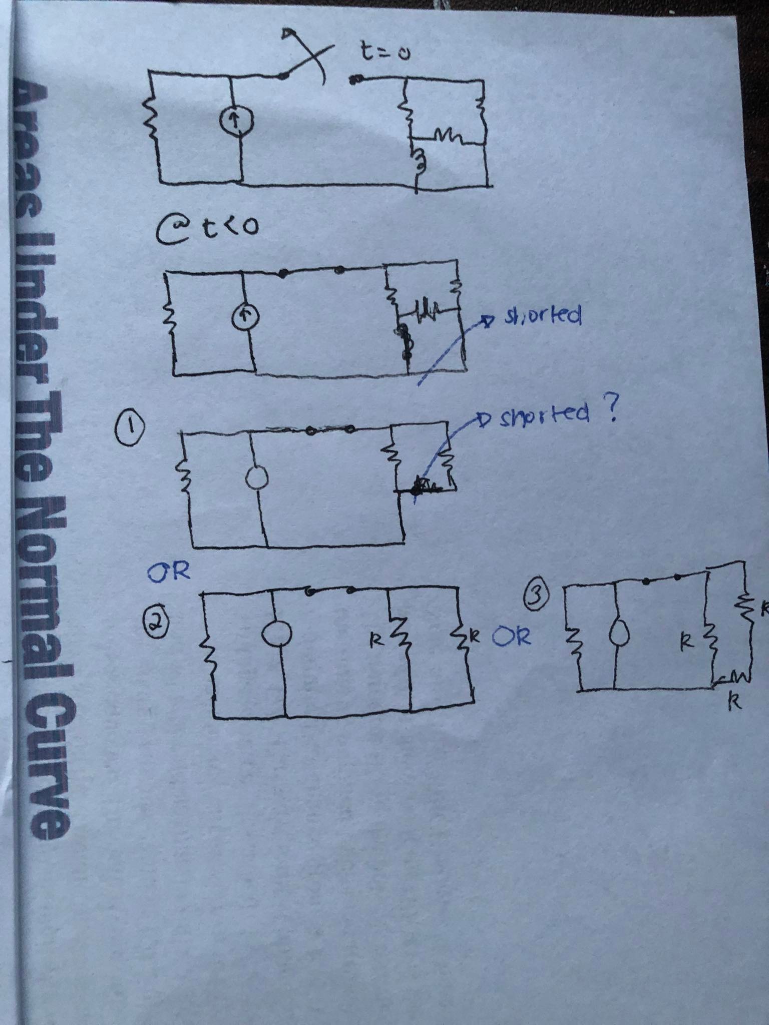
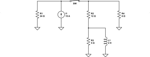
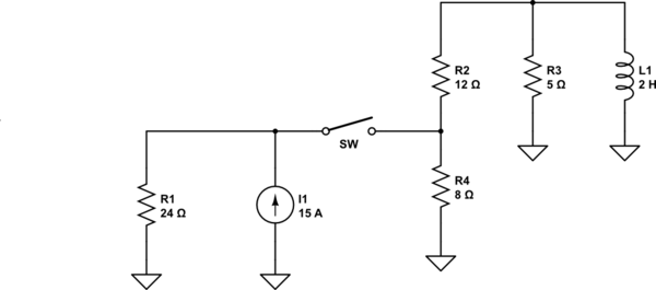
Knowing all that, your circuit can be reconstructed, in a step by step manner, removing any short-circuited components one by one. Start by shorting the inductor here:
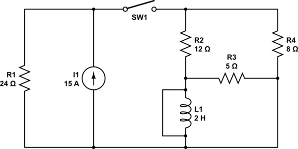
simulate this circuit
Remove the inductor, leaving only the short circuit path:
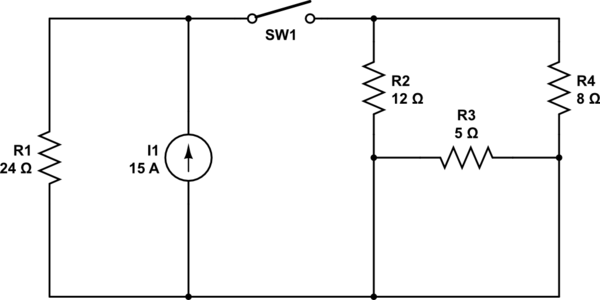
simulate this circuit
Notice that R3 is now also short-circuited, so remove that too, leaving only the short-circuit path in place:
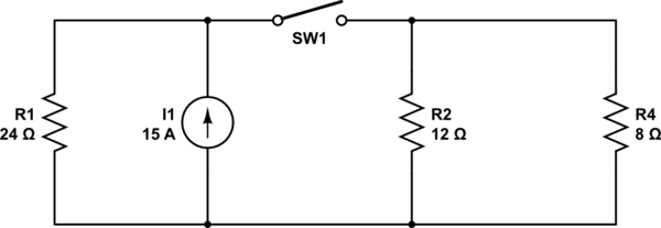
simulate this circuit
Notice how R2 an R4 are now in parallel and can be replaced by a single resistance. I won't do that here, you get the idea.
Proceed like this until you have a minimal circuit, then perform your analysis.


