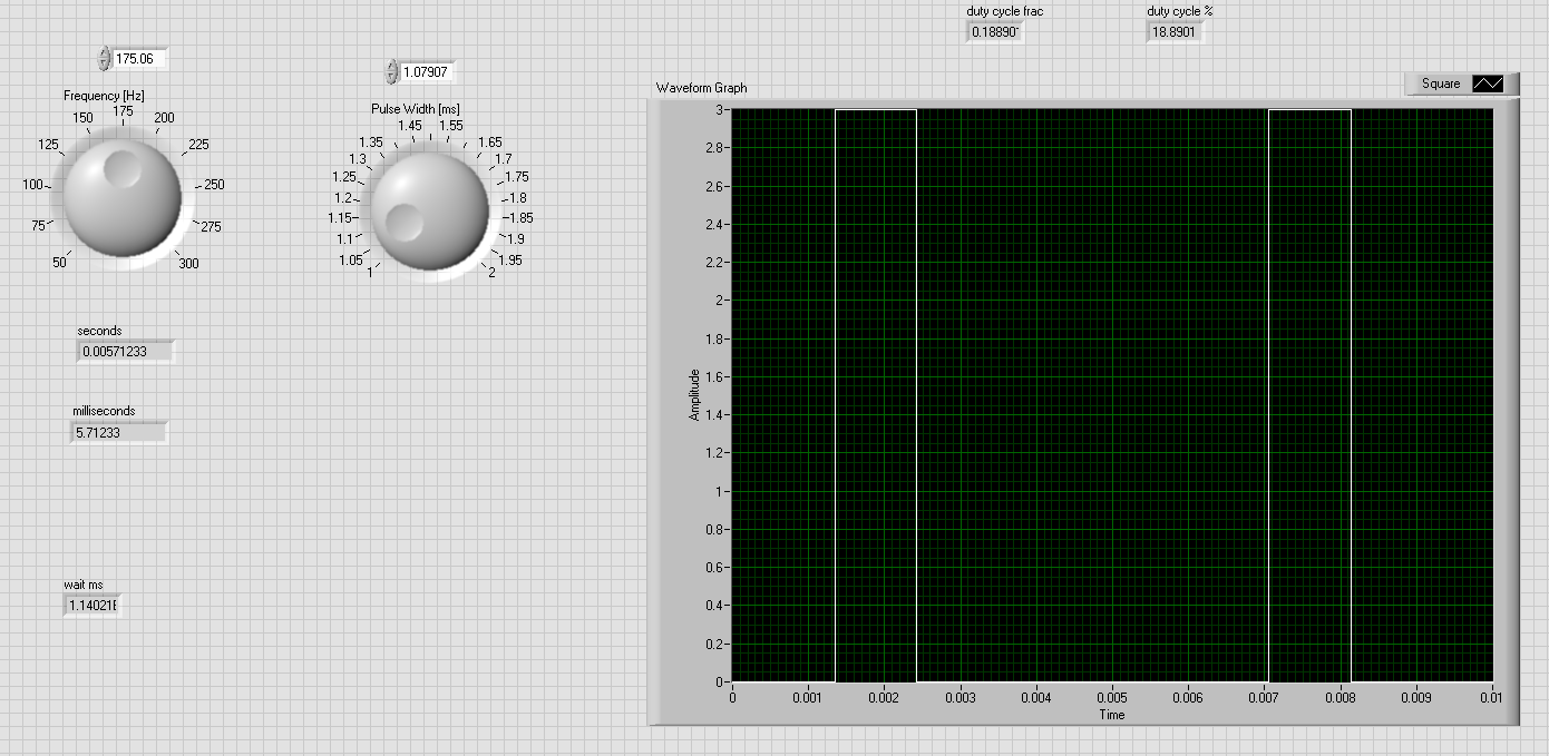
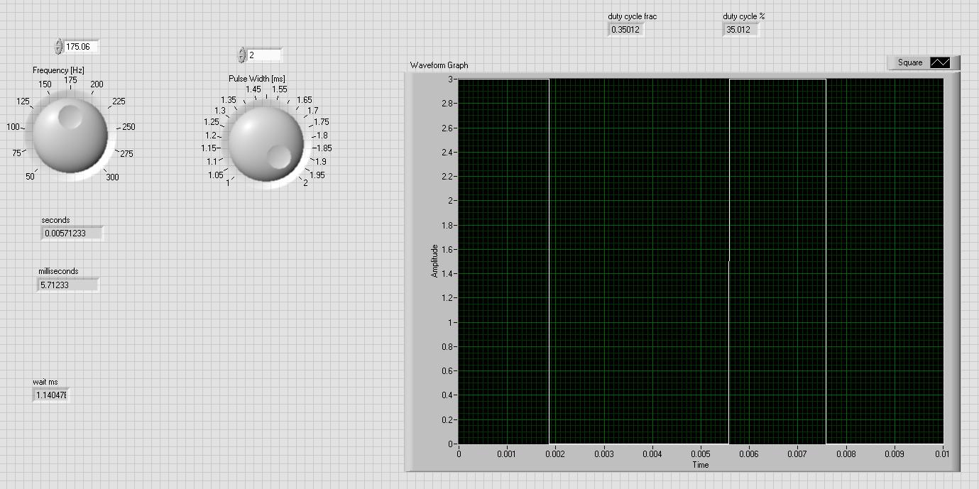
I have created the following LabVIEW GUI to generate a square pulse train waveform:

As you move the frequency and pulse width knobs the waveform changes accordingly (pulse width is now 2ms).

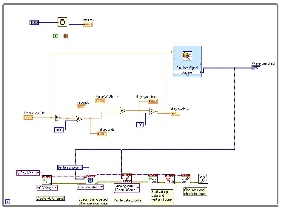
I used the following back panel diagram to drive the logic:

I have a PCIe-6259 DAQ card that is supposed to convert the waveforms above into analog output.
I used this video tutorial to design the wiring diagram logic shown above.
If you look at the "AO Voltage" control in the wiring diagram you will see it has "Dev1/ao1" selected for analog output.
The DAQ is connected to a BNC 2110 that has the Analog Output #1 terminal.
I wired the Analog Output terminal #1 to the oscilloscope to channel 1 but I do not see any square wave pulses. What am I doing wrong?
How do you debug something like this?
