1
\$\begingroup\$

I have an IR photodiode, part number PDB-C134F, as shown here. I'm trying to use it to retransmit a remote control signal that uses a carrier frequency of 38 to 40kHz. However, when I connect the diode to an oscilloscope and look at the received signal, the carrier is lost. I simply see a square wave encoding the data (with a pulse width of 0.5ms and an amplitude of about 0.4V) but no finer square wave (which should have a pulse width of around 12us). My oscilloscope is very basic (the Xminilab), but it is sampling at 2MS/s, and is rated at 200kHz, so I would think that it should be able to see the signal. It can see a 40kHz signal that it generates on its waveform generator output.

In my test, the diode pins are connected directly to the scope inputs, and there are no other elements in the circuit. I've also tested it after amplification with an opamp, and see the same thing.

Am I misunderstanding how this part works? Or misusing it or the scope?

Thanks for any advice!

\$\endgroup\$

2 Answers 2

4
\$\begingroup\$

Probably the photodiode is acting (with the 'scope input capacitor) as a rectifier for its own signal.

Photo current will only flow one way from the photodiode. This will charge up the input capacitor of the 'scope. When no light is present, the charge will only bleed away slowly through the scope's input resistance, which is maybe 1 or 10 megohms.

Apparently the bleed is fast enough to let you see the data signal, but not fast enough to let you see the 38 kHz carrier.

As for a solution, try adding some lower-value bleed resistor (maybe 1 kohm), but realize this will likely also reduce the signal amplitude, maybe too low to measure. If that's the case, you'll need to build a real bias circuit or even a transimpedance amplifier to condition the output of the photodiode before measuring it.

\$\endgroup\$
1
  • \$\begingroup\$ Thanks! Using a 3k resistor in parallel with the photodiode, I could see the carrier signal, although it was quite smoothed out. \$\endgroup\$ Commented Sep 4, 2015 at 0:30
2
\$\begingroup\$

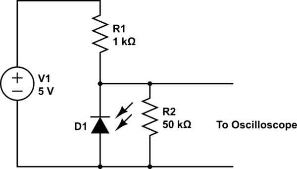
schematic

simulate this circuit – Schematic created using CircuitLab

As explained by The Photon, signal is getting filtered due to high input impedance of the scope.

Another solution is as follows: Give a simple bias to the IR photodiode. Usually they have off resistances ranging from 10K~100K (depending on their make and ambient IR). This will provide you a signal with measurable amplitude and strength.

\$\endgroup\$
2
  • \$\begingroup\$ Thanks for the suggestion. I'm sure that something like this would work, but with the resistor values suggested, I couldn't see any signal at all. With some other values, I could see the data signal, but I couldn't see the carrier. \$\endgroup\$ Commented Sep 4, 2015 at 0:33
  • \$\begingroup\$ I think it has more to do with the scope limitations. \$\endgroup\$
    – tEddy
    Commented Jun 16, 2016 at 16:35

Your Answer

By clicking “Post Your Answer”, you agree to our terms of service and acknowledge you have read our privacy policy.

Not the answer you're looking for? Browse other questions tagged or ask your own question.