I want to mount a brushed DC motor on a bike and drive it with PWM. I know I could directly use a PWM generator IC, a 555 timer, use an Arduino or use an already made DC motor driver, but I want to build the circuit myself.
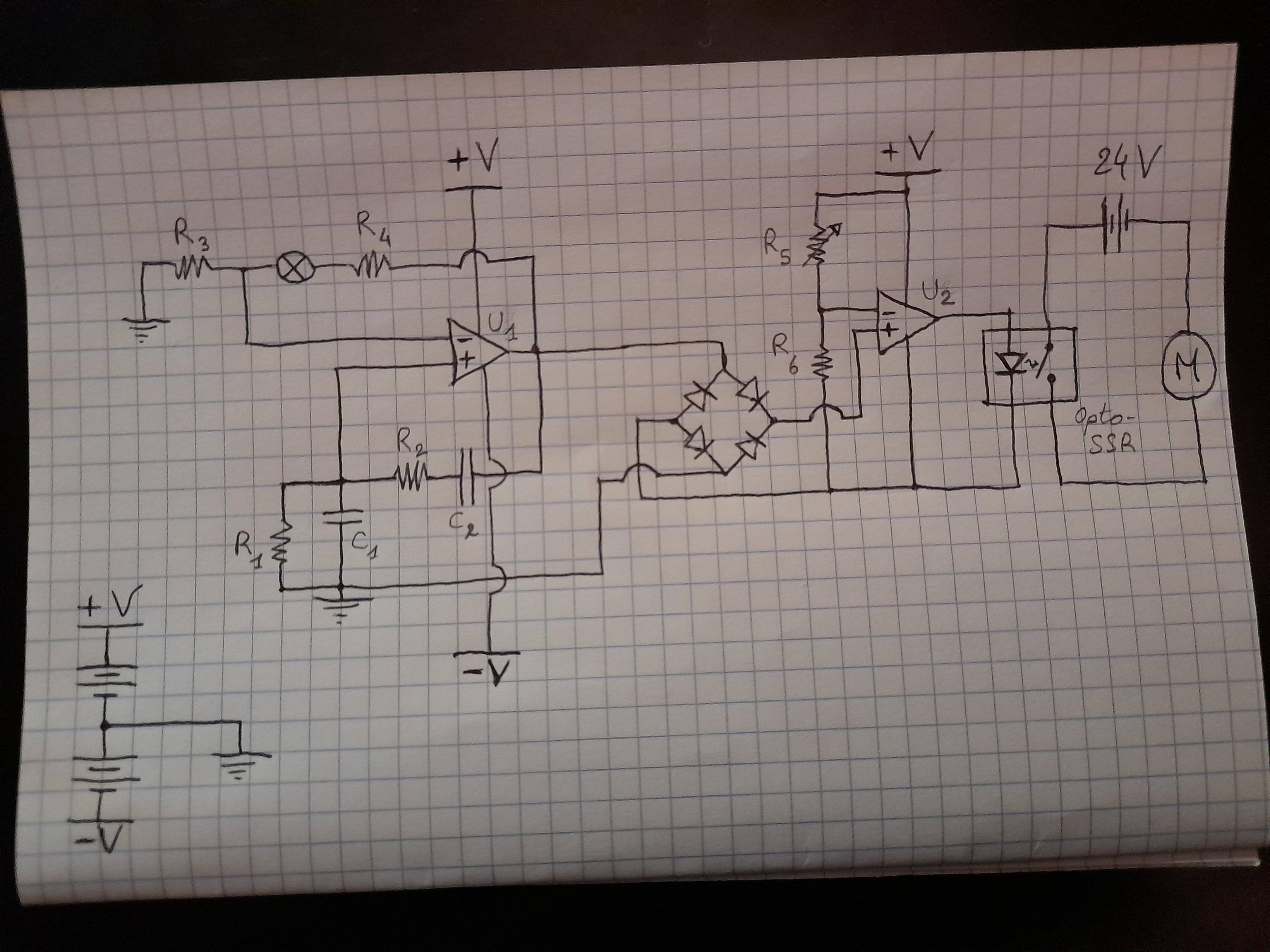
Attached is the circuit I imagined:
An RC oscillator generates a sine wave signal (output of U1) that is rectified through a full bridge rectifier and is then fed along with a fixed voltage into a comparator (U2) to generate a PWM signal. This PWM signal then actuates an opto SSR that drives the motor. R5 potentiometer would act as the "throttle" of the motor, varying the reference voltage and therefore the duty cycle value of the PWM signal.
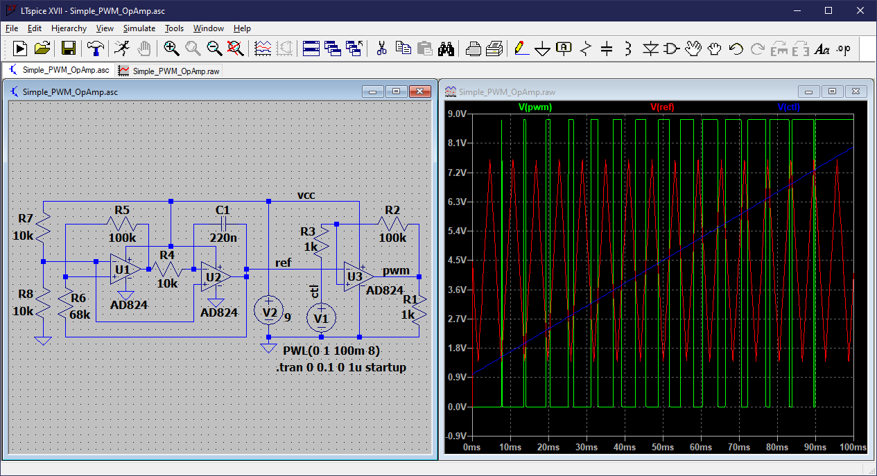
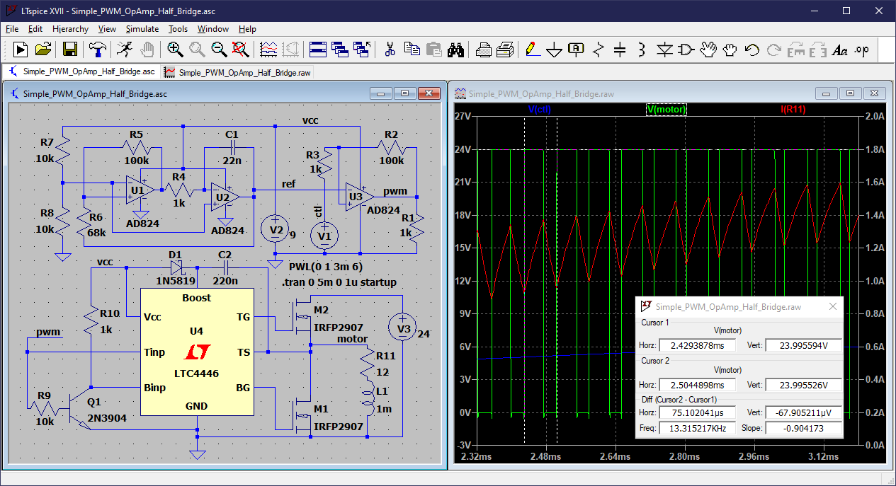
I also attached an LTSpice simulation file I made (took the oscillator part from the internet). I had to add a few things to make it kind of work, mainly resistors and a buffer opamp between the rectifier and U2. Here is the google drive link : https://drive.google.com/file/d/14ZA4uFyuyh9bzQHPsTTj34qJEv0vY_dM/view?usp=share_link
I am very new to circuit design and started dabbling in electronics only recently (I have a materials engineering background).
Here are my main questions/concerns:
Since both the PWM generator circuit and the motor circuit would run on batteries, would the grounding as I've drawn it on paper work? (I think common is more appropriate in that case) Grounding in LTSpice is complicated with full bridge rectifiers and I'm having a hard time understanding it.
Could the PWM generator circuit be run on low voltage batteries? (I was thinking about 9V batteries?) My guess is that I would have to take into account the voltage drop across the diodes as well as the voltage needed for the opto SSR to turn on.
I've seen on the internet that a good PWM frequency is around 25 kHz and above, as it's beyond human hearing range. Do you think an opto SSR could switch that fast? I've read that their weakness is switching speed.
An H-bridge is unnecessary to drive the motor since I only want forward motion, is that right?
All in all, do you think this is realistic and would work in real life? I have never built real circuits, so I don't have a reference when it comes to real circuits behaviours (signal distortions, losses, heat dissipation, power supplies stability etc).
If you think I could give this circuit a try, could you please give me the names of parts you would recommend for this job? (especially opamps and opto SSR).
I would run the motor with two 12V lead-acid batteries in series. Here are the specs of the motor: https://www.lynchmotors.co.uk/pdfs/lmc-lem-130.pdf
LEM-130 95 motor from LynchMotors:
- 2.27 kW rated power (3 kW peak)
- 75 A rated current (100 A peak)
This is for 65V, so I guess for 24V it would be less than half current and power?
Please be critical and give me your guidance regarding this circuit. Any advice will be greatly appreciated.


