2
\$\begingroup\$

enter image description here

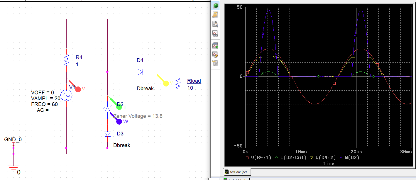
I'm looking for a circuit that can clip the peaks of a sine wave source, typically the source is 40 V peak to peak and should be clipped at about 13.8 V. The circuit below does exactly this but to my knowledge there are no Zeners that'll be able to handle the 50 W or possible larger peaks. The idea will be use power MOSFETs or BJTs attached to a heatsink to clamp the peaks.

This will be used to clamp the generator output on a gasoline engine, the kind of regulators used on these generation of engines are pretty bad and cooks the battery, I'm attempting to fix this problem. The generator won't be damaged by clamping the output.

Edit: Added the half bridge diode for Rload to make everyone in the comments happy :D

\$\endgroup\$
8
  • 1
    \$\begingroup\$ Are you trying to use a fossil-fuel generator that produces AC (kind of) with about 20 V peaks in order to charge up 12 V lead acid batteries?? Because, if so, the first thing to do is to use a bridge rectifier on the darned thing, I'd imagine. \$\endgroup\$
    – jonk
    Commented Dec 17, 2022 at 3:26
  • \$\begingroup\$ Yes and no, the one AC wire is already ground everywhere on all the electricals and the bridge rectifier won't like that. Just going with half bridge at this stage. \$\endgroup\$
    – Ne3M
    Commented Dec 17, 2022 at 3:34
  • \$\begingroup\$ I'm not understanding why both the generator AND ALSO the battery must be wired 'single-ended' like that. Can't you either lift the generator away from the ground or else lift the battery away from the ground? If not, exactly why not? What's the reason one end of BOTH of them MUST be tied together? Put another way, if the generator had a bridge rectifier on it, why couldn't the battery be tied to the other side of the bridge? I'm sure there's a good reason. But I'm not seeing anything that I couldn't fudge somehow in order to make it work, right now. \$\endgroup\$
    – jonk
    Commented Dec 17, 2022 at 3:38
  • \$\begingroup\$ You need at least a diode in series with the battery... otherwise it will be runing current through the battery backwards, no wonder why it would cook the battery. \$\endgroup\$
    – Voltage Spike
    Commented Dec 17, 2022 at 3:55
  • 2
    \$\begingroup\$ You just would not do it the way you propose (XY problem until such details arrive that justify this method). \$\endgroup\$
    – Andy aka
    Commented Dec 17, 2022 at 8:26

2 Answers 2

2
\$\begingroup\$

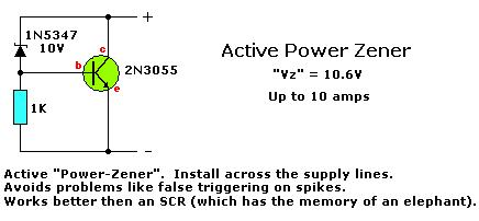
The circuit to do this with a bipolar power transistor has been around since the 1950's. In your case, I would use a power Darlington.

If you replace the zener diode with a pot in series with a fixed resistor, you have an adjustable zener. The circuit often appears in audio power amplifier designs, where you can adjust the voltage spacing between the output transistors to set the no-signal static current through them.

http://www.seekic.com/circuit_diagram/Basic_Circuit/Active_Power_Zener.html

enter image description here

UPDATE:

This circuit replaces only D2 in your original circuit. D3 still is needed.

\$\endgroup\$
5
  • \$\begingroup\$ This is exactly what I was looking for, thank you so much! \$\endgroup\$
    – Ne3M
    Commented Dec 17, 2022 at 13:38
  • \$\begingroup\$ D3 is there to compensate the temperature coefficient of the zener diode, and it might be omitted if some drift with temperature is acceptable. On the other hand the base-emitter junction has the same effect in your proposed circuit. Therefore I am not sure why have you stated that D3 is still needed. \$\endgroup\$ Commented Dec 17, 2022 at 22:23
  • \$\begingroup\$ Disagree. See Update-2. \$\endgroup\$
    – AnalogKid
    Commented Dec 18, 2022 at 15:08
  • \$\begingroup\$ @Ne3M That's not what you're looking for if you don't want to waste lots of power. This circuit is excellent for clamping occasional transients. You have an AC source so there are no "transients": voltage peaks are inherent, and dumping them as heat by active shunting will overload the generator! Do not do it this way. \$\endgroup\$ Commented Dec 19, 2022 at 23:57
  • \$\begingroup\$ The circuit in the original post is a shunt regulator. This circuit is a shunt regulator with a low-power adjustability feature. AND - there is explicit signoff on the signal/power source loading issue. An alternative would be a low dropout series regulator, but that is a more complex circuit. \$\endgroup\$
    – AnalogKid
    Commented Dec 20, 2022 at 22:20
1
\$\begingroup\$

I'm looking for a circuit that can clip the peaks of a sine wave source, typically the source is 40 V peak to peak and should be clipped at about 13.8 V.

This is not a particularly great idea, as you'll be wasting energy as heat - and that's a rather expensive energy, since it comes from an ICE.

A switching buck DC/DC converter would be ideal, but a linear regulator can do the job as well, while wasting less heat than a shunt would, especially at lighter loads (e.g. when the battery has charged up).

In essence, all you need is a linear regulator with reasonably low dropout, set to 13.8V. The circuit below does this:
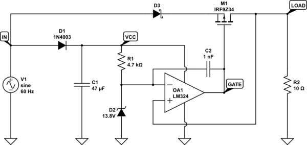
schematic

simulate this circuit – Schematic created using CircuitLab

The voltage waveforms on named nodes are shown below.

Voltage waveforms

The average power dissipated on the pass element and the Schottky series diode, with a 10 Ohm load, is a couple Watts total:

Power dissipated on the pass element and the rectifier diode

With two mosfets, rectification can be active, for lower dropout, but most likely this won't be of any advantage in this applicaiton:
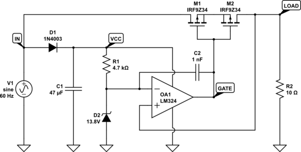
schematic

simulate this circuit

A battery charger of this kind also requires active current limiting, to protect itself, the load, and the generator's winding from short circuits and overload.

The easiest way to get such protection is with a thermal circuit breaker. It could also be implemented electronically.

One way uses the series rectifier diode as a current sensor. A second, matched diode, running at a small constant current, needs to be thermally coupled to the rectifier diode. The difference between these voltages is a measure of the logarithm of the current ratio between the two diode.

Another approach is to use the Rds(on) resistance of the mosfet. This is straightforward when the mosfet is fully turned on. With two mosfets, we can decouple their control and use one as an ideal diode, acting as a current sensor when turned on, and the other as the pass element. The ideal diode doesn't require a heatsink, since it has negligible losses - this way it also stays at a temperature that's relatively independent of the load current. Then we don't need a third reference mosfet to establish Rds(on) scaling.

\$\endgroup\$
1
  • \$\begingroup\$ This is a really great solution, thanks for your input! \$\endgroup\$
    – Ne3M
    Commented Dec 22, 2022 at 1:39

Your Answer

By clicking “Post Your Answer”, you agree to our terms of service and acknowledge you have read our privacy policy.

Not the answer you're looking for? Browse other questions tagged or ask your own question.