0
\$\begingroup\$

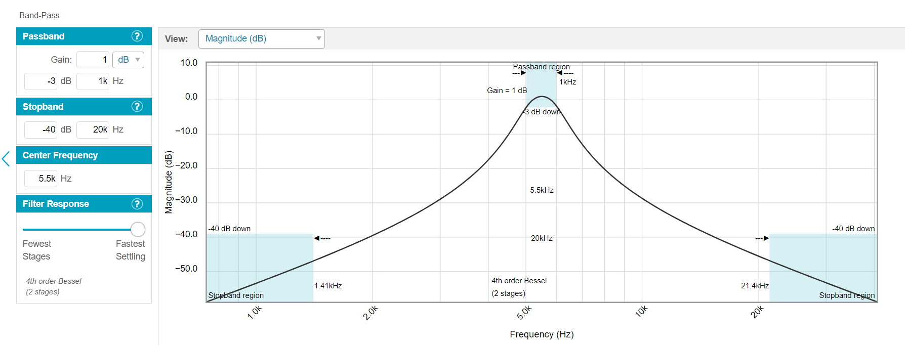
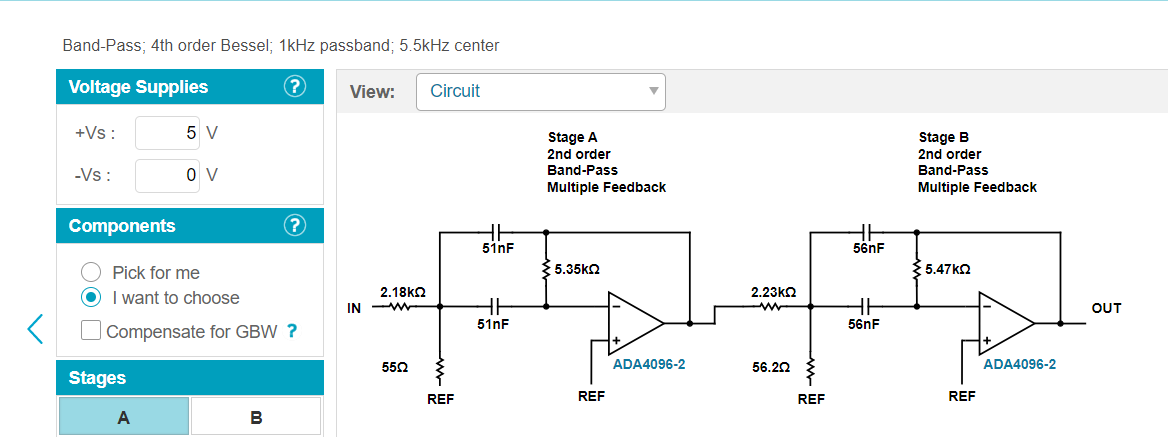
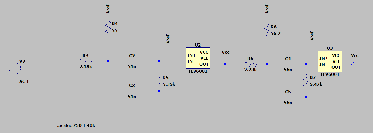
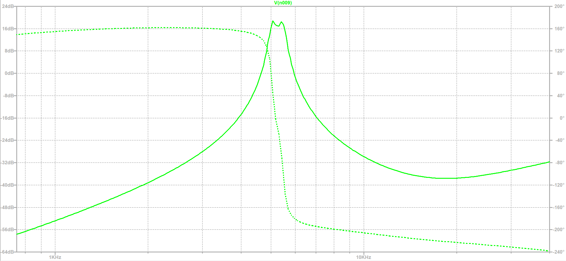
I want a band pass filter with center frequency 5.5Khz and a passband of 1kHz. I inserted that into a website and got the frequency response and the components to implement the filter:

enter image description here

enter image description here

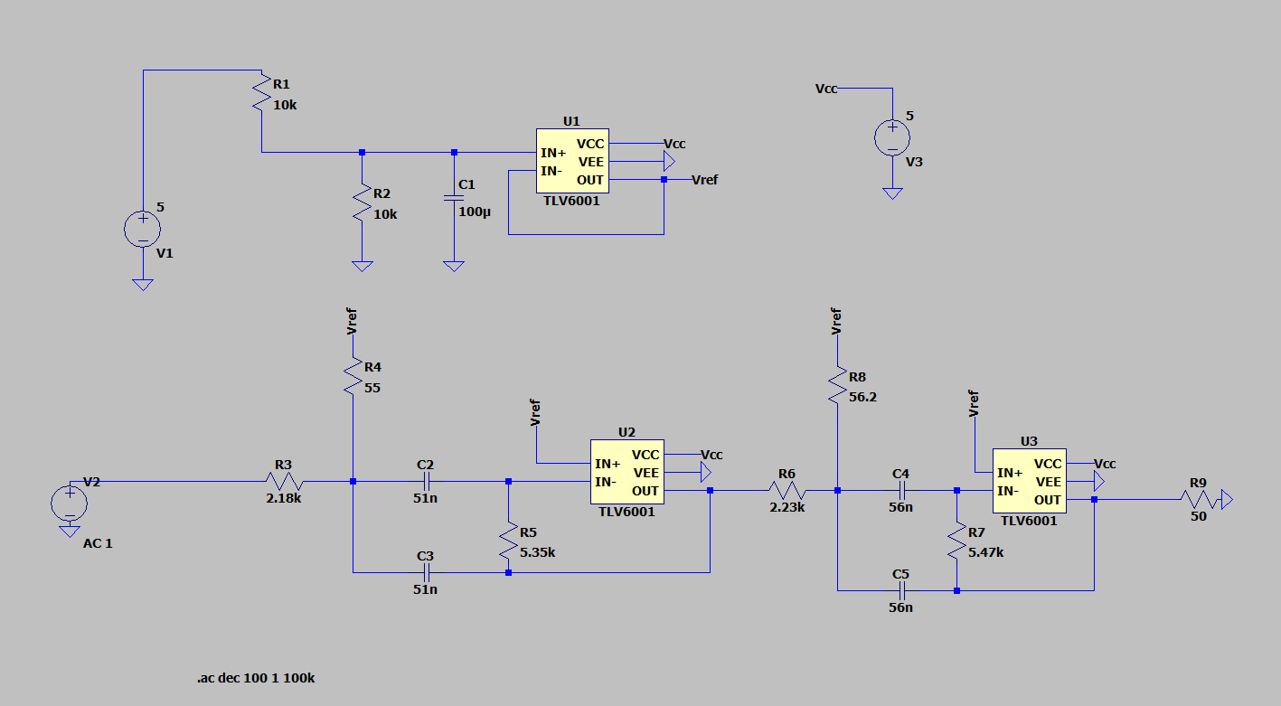
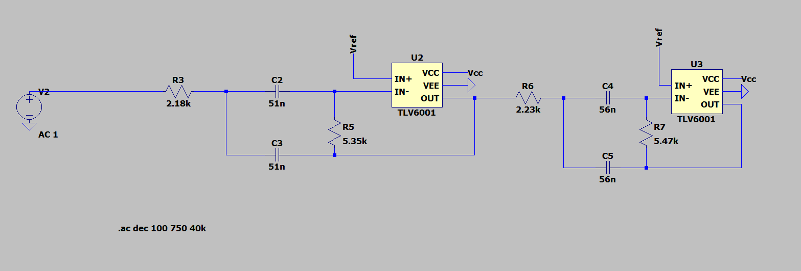
I copied the circuit to LTSpice (with a different op amp):

enter image description here

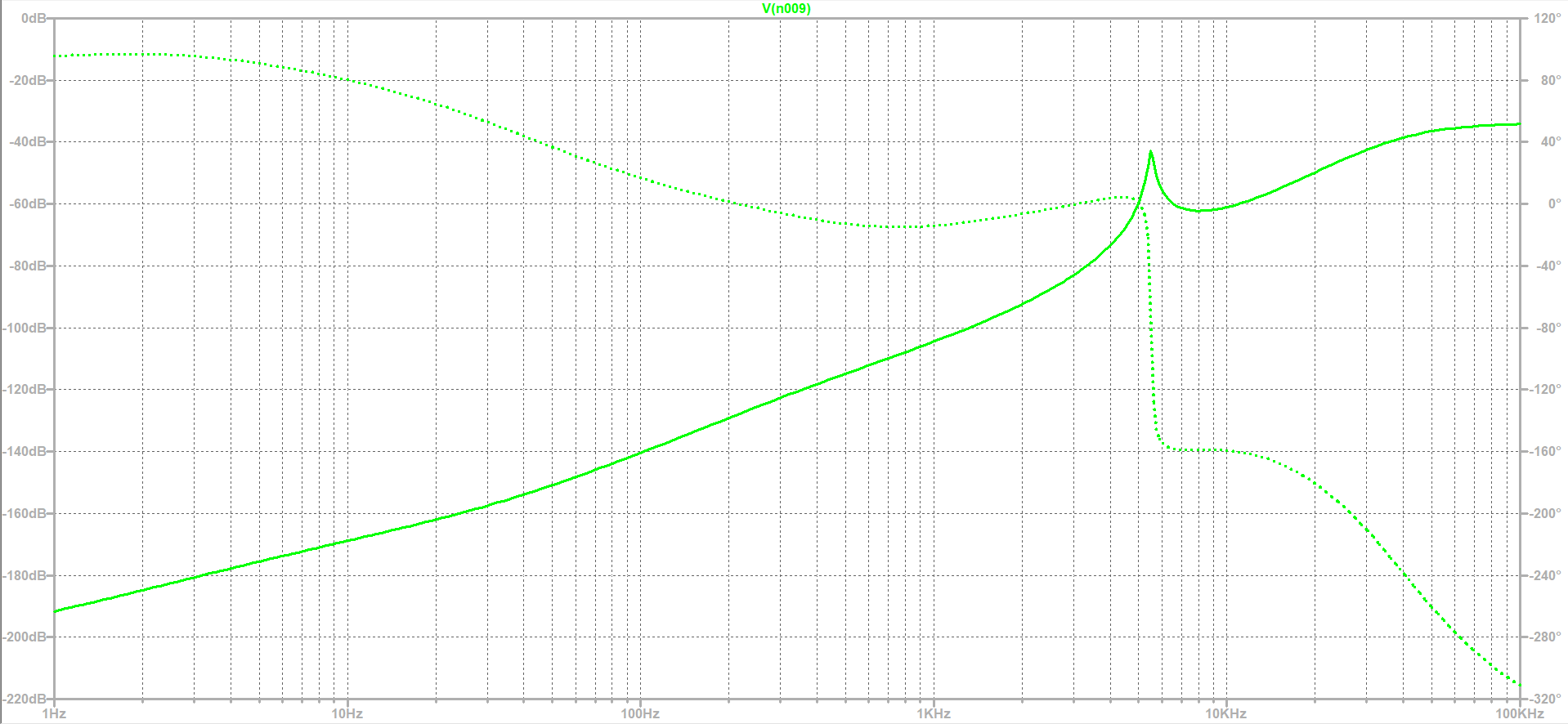
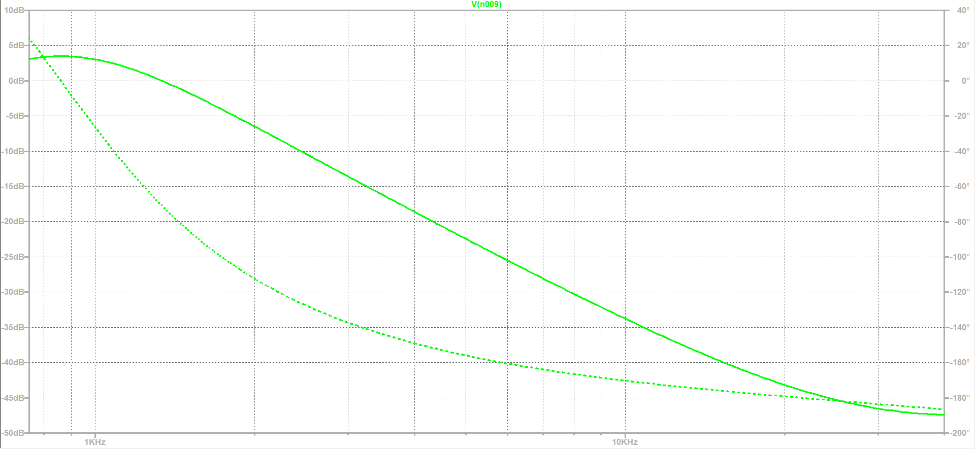
And got this frequency response:

enter image description here

Why is it so different from the one shown at that website?

Edit:

So if i take the load:

enter image description here

enter image description here

It's better but now the gain is very high at the center frequency

If i take the resistors connect to Vref:

enter image description here

enter image description here

The center frequency seems to shift to 1kHz

\$\endgroup\$
7
  • \$\begingroup\$ Is that a 50 Ohm load I see there? (Haven't even looked at the TLV6001, yet.) \$\endgroup\$
    – jonk
    Commented Dec 17, 2022 at 16:20
  • \$\begingroup\$ You should not have R9, however I doubt that is the entire problem. I'm suspicious of the 55 and 56.2 ohm resistors, remove them from your simulation and see what happens. TLV6001 should have sufficient GBW for the centre frequency, but it might be marginal on Q. \$\endgroup\$
    – Neil_UK
    Commented Dec 17, 2022 at 16:24
  • \$\begingroup\$ @jonk yes it is and i already tried to do a simulation without it \$\endgroup\$
    – Scipio
    Commented Dec 17, 2022 at 16:31
  • 2
    \$\begingroup\$ You should not be taking out R4 and R8 entirely -- they're there for a reason. However, since they are AC coupled to the op-amps, you can bring them to ground. The TLV6001 has an open-loop output impedance of \$2300 \Omega\$ and a GBW product of 1MHz -- so at the nominal 5.5kHz loop closure frequency they'll have an inductive reactance of 12 to 13 ohms. With the not-much-higher impedances of R4 and R8, this will cause weird coupling between the stages, and won't quite be ground. \$\endgroup\$
    – TimWescott
    Commented Dec 17, 2022 at 17:15
  • 2
    \$\begingroup\$ Given the rated open-loop output impedance of that particular amplifier, it may be profitable to multiply all of your impedances by 10, or even 100 (i.e., increase the resistances by a factor of \$k\$, and decrease the capacitances by the same amount). Doing so may let you bring R4 and R8 to \$V_{ref}\$ without weird things happening -- or at least, with less weird things happening. \$\endgroup\$
    – TimWescott
    Commented Dec 17, 2022 at 17:17

5 Answers 5

1
\$\begingroup\$

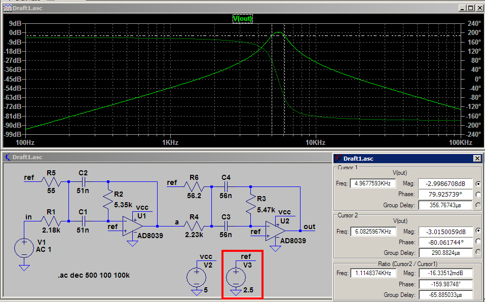
An LTspice simulation of the circuit is very similar to the simulated results from the reference Web site. Perhaps the opamp models you are using are bad (model faulty, subcircuit(s) not constructed properly, ...). Many things can go wrong when importing 3rd party models. Have you tried a simple amplifier using the model you are using? If not, you need to do this to verify that the model is behaving as expected.

The following is a filter with a perfect Vref supply that is outlined with the red box. When doing SPICE simulations, go for the basics first, then add on the frills. I used one of the opamp models that comes with LTspice that I know works.

enter image description here

\$\endgroup\$
0
\$\begingroup\$

Results from analog simulators such as SPICE are totally dependent on how the components are modeled. This probably explains why your results are different with two different simulators. Also, keep in mind that these are simulations and my experience is that many times they give different results than what you see in a real circuit.

\$\endgroup\$
0
\$\begingroup\$

Two grounded resistors are missing and a +2.5V fairly low impedance REF is not shown. bandpass

\$\endgroup\$
0
\$\begingroup\$

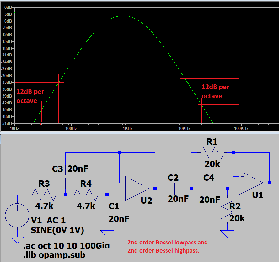
The cascaded Multiple Feedback Bandpass Filters are not Bessel. Bessel slopes are gradual and droopy but with a low phase shift.

Here is a 2na d order bandpass filter made with a Sallen-Key Bessel lowpass and a BesselBessel highpass:

\$\endgroup\$
-1
\$\begingroup\$

The Wizard shows levels from +10dB to -60dB which total 70dB. You show levels from 0dB to 220dB!

The Wizard shows frequencies from 750Hz to 40kHz. You show frequencies from 1Hz to 100kHz!

\$\endgroup\$
2
  • \$\begingroup\$ Even taking that into account things still are very different from one another \$\endgroup\$
    – Scipio
    Commented Dec 17, 2022 at 16:22
  • \$\begingroup\$ (Downvoters please comment what makes this answer not useful.) \$\endgroup\$
    – greybeard
    Commented Dec 17, 2022 at 17:27

Your Answer

By clicking “Post Your Answer”, you agree to our terms of service and acknowledge you have read our privacy policy.

Not the answer you're looking for? Browse other questions tagged or ask your own question.