0
\$\begingroup\$

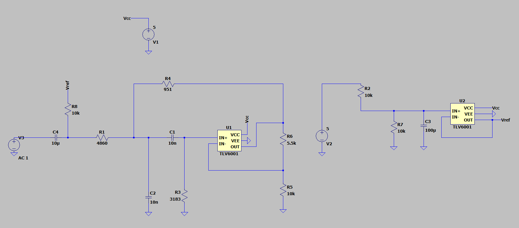
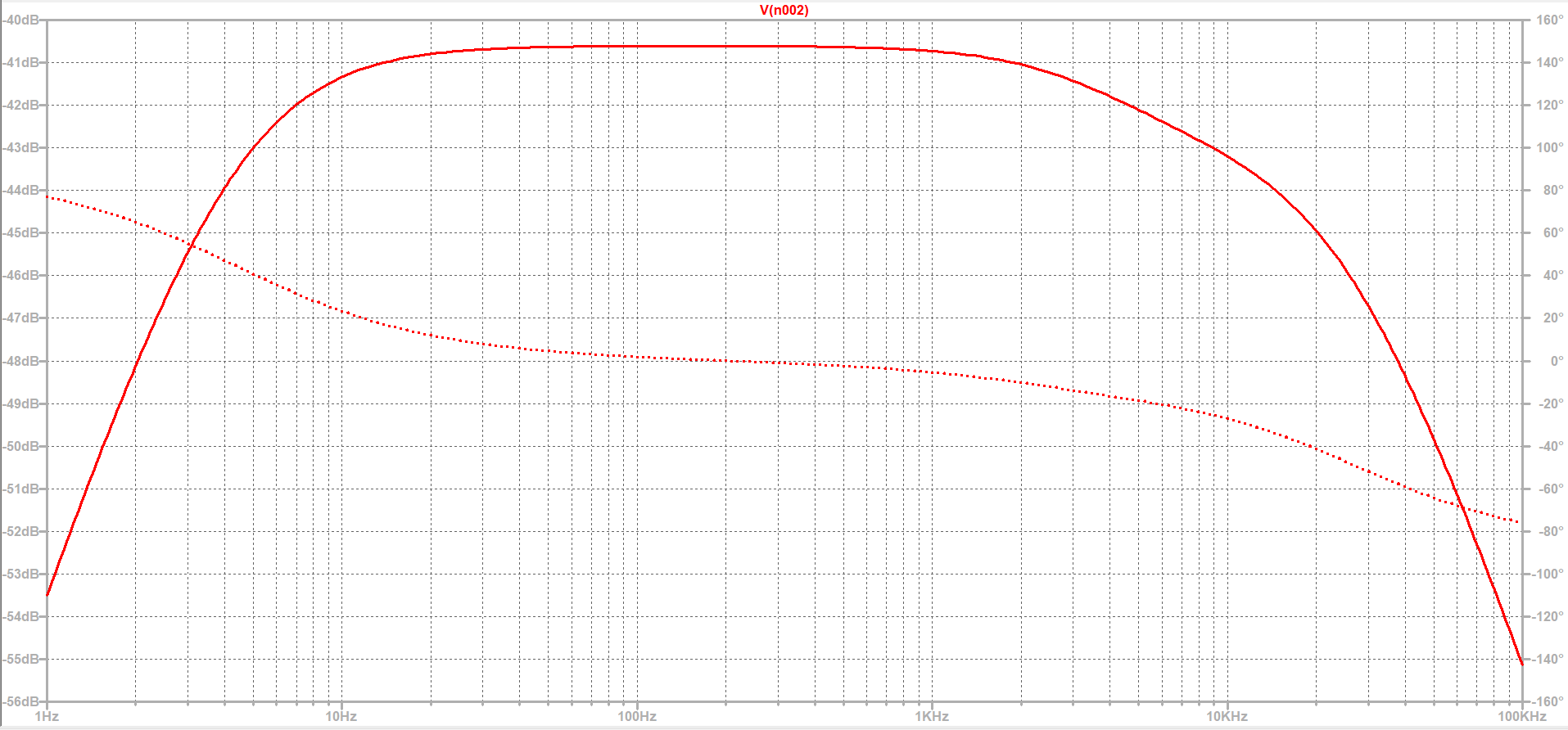
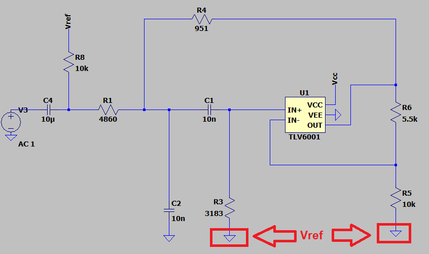
I'm trying to develop a band pass filter with center frequency 10 kHz:

enter image description here

enter image description here

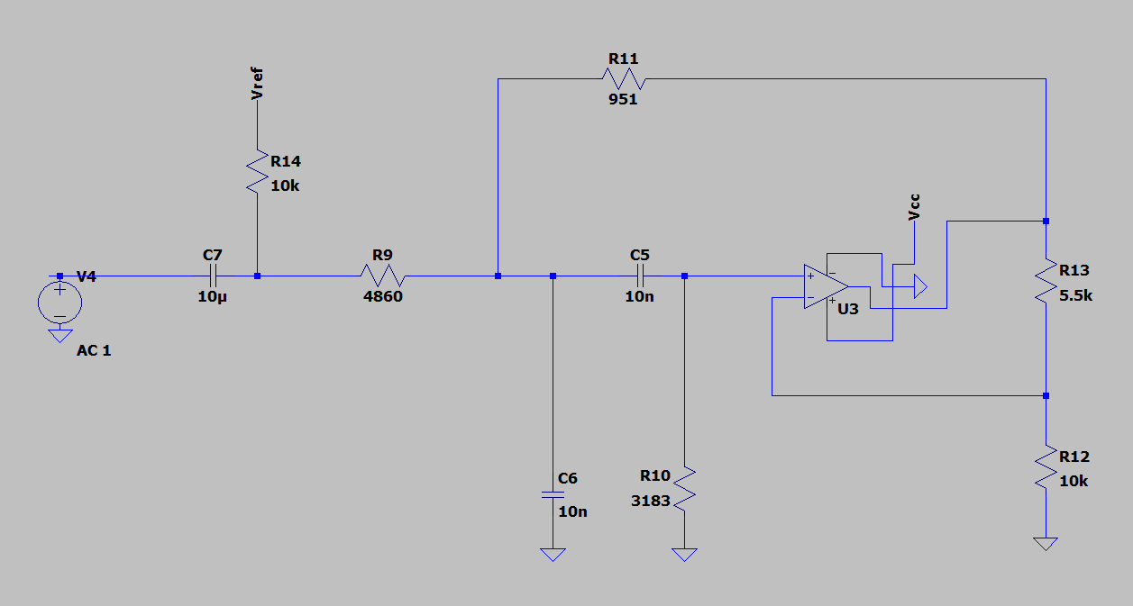
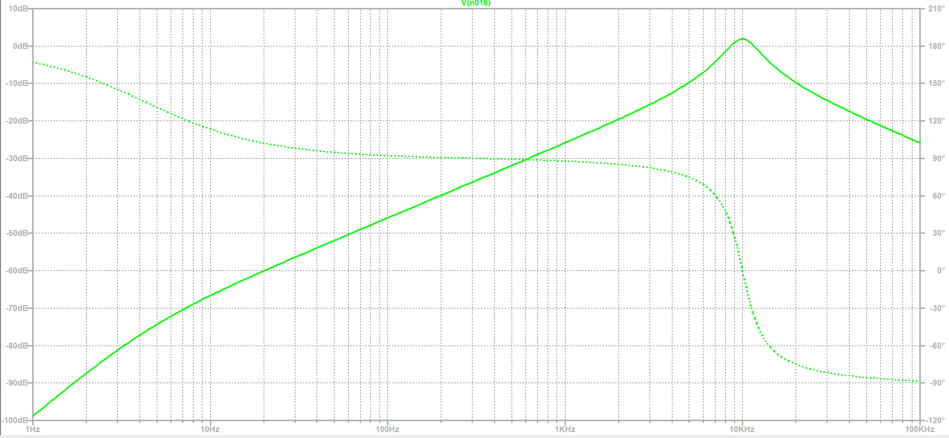
The frequency response doesn't look good, but when i replace the circuit above with an ideal op-amp, I have the correct response:

enter image description here

enter image description here

Why doesn't the filter circuit with the real op-amp work as intended?

\$\endgroup\$
2
  • \$\begingroup\$ At first you should read the datasheet of the used real op amp very carefully and compare it with the requirements of your circuit. \$\endgroup\$
    – Uwe
    Commented Dec 11, 2022 at 13:24
  • \$\begingroup\$ @anilberg I have rejected your edit because it obscures the meaning of band pass filter (by abbreviation) and incorrectly renames "op-amp" as "OpAmp" \$\endgroup\$
    – Andy aka
    Commented Dec 11, 2022 at 13:53

1 Answer 1

1
\$\begingroup\$

Why isn't the frequency response of this band pass filter circuit the same as the band pass filter with an ideal op amp?

You need to make the following changes: -

enter image description here

An ideal op-amp won't care what the power rails are or where the resistors above are connected to in terms of DC level.

\$\endgroup\$

Your Answer

By clicking “Post Your Answer”, you agree to our terms of service and acknowledge you have read our privacy policy.

Not the answer you're looking for? Browse other questions tagged or ask your own question.