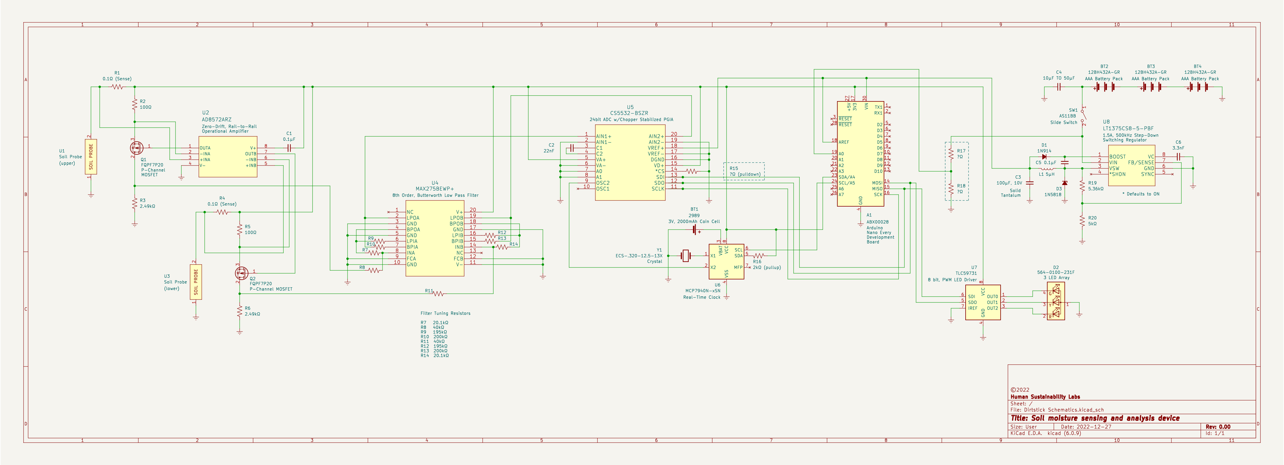
Below you will find a buffet of questions and the schematic for my device. (Click on it and you will get the full-size image.) Please tear this up. I'm a self-taught novice putting together a high-precision device. Can you help me validate the circuit?
- There is a pull-down resistor (R15) at location B7 on the schematic, I need help calculating the value.
- I have access to SPICE, would this kind of circuit be suitable for simulation?
- Where have I failed to follow standards?
- Which capacitors are bypass, blocking or coupling?
- The ADC and the LED driver both communicate with SDI/SDO. Can I serve both components on the single input/output of the development board? (Location B8.)
- Can I use different color lines to represent signal and communications?
- I need help calculating the voltage divider for an output that is 1/4 of the input (R17/R18 at location B9).
The component labeled soil probe is under development. Essentially, at this point in time, I am using the sub-circuits at the left side of the schematic to create two separate precision current meters where the load is the dirt. I got the circuit from page 22 of the op-amps datasheet.
Datasheets for all the major components follow:

