1
\$\begingroup\$

Recently, I have been given a task at the place where I am serving my internship. I have been given a pair of TTGO LoRa32 T3 V1.6.1 boards which house ESP32 microcontrollers and my task is to connect an ENC28j60 Ethernet module to these to send the data with the LoRa module that has been acquired from the Ethernet module through the web (I guess).

I am relatively new to these modules and need some help.

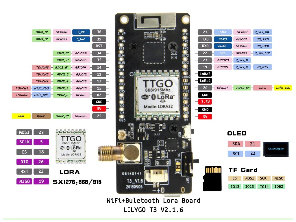
First, this is the Dev Board:

enter image description here

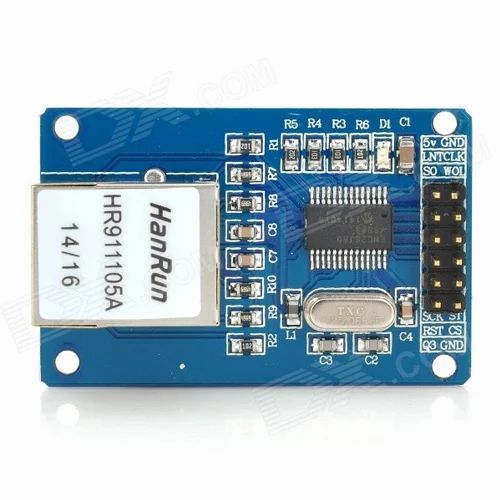
And this one is the Ethernet module:

enter image description here

From what I can see the Ethernet module has SPI pins in order to communicate with the MCU, but I don't know which of the physical pins on the board are MOSI, MISO, CS, and CLK. There are some pins with SPI labels but I can't understand the notation like V_SPI_WP or V_SPI_Q. There are also some pins at the lower left side of the pinout diagram but these are the internal connections of the LoRa module to the MCU. How can I connect this Ethernet module to the board?

\$\endgroup\$
2
  • \$\begingroup\$ When given a board, you need to either try find the documentation yourself, or failing that, ask for documentation from the person who gave you the boards. What have you done to try finding documentation? \$\endgroup\$
    – Justme
    Commented Dec 30, 2022 at 13:39
  • \$\begingroup\$ Only documentation I can find is the pinout diagram and that is not helpful, I tried to look at the pinout of the ESP32 itself and I can see up to 4xSPI support but I can't know the peripheral configuration of the MCU therefore that wasn't helpful either. I don't think "the person" knows it either, because he told me to find it from the internet... \$\endgroup\$
    – Jupiterian
    Commented Dec 30, 2022 at 13:58

2 Answers 2

3
\$\begingroup\$

Per the ESP32 Pico D4 datasheet, peripherals are the same as the original ESP32.

And per the linked ESP32 datasheet, more details can be found in the ESP32 Technical Manual:

ESP32 integrates four SPI controllers which can be used to communicate with external devices that use the SPI protocol. ... The SPI signal buses consist of D, Q, CS0-CS2, CLK, WP, and HD signals, as Table 7-1 shows.

(page 117)

and

The SPI controller supports four-line full-duplex/half-duplex communication (MOSI, MISO, CS, and CLK lines) and three-line half-duplex-only communication (DATA, CS, and CLK lines) in GP-SPI mode. In QSPI mode, an SPI controller accesses the flash or SRAM by using signal buses D, Q, CS0 ~ CS2, CLK, WP, and HD as a four-bit parallel SPI bus. The mapping between SPI bus signals and pin function signals under different communication modes is shown in Table 7-1.

But per the board design:

Pin Function
I018 LoRa NSS/SEL
IO5 LoRa SCK
IO27 LoRa MOSI/SDI
IO19 LoRa MISO/SDO
IO26 LoRa DI0/IO0
IO13 SD CS
IO2 SD MISO
IO15 SD MOSI
IO14 SD SCK
IO12 SD DATA2
IO4 SD DATA2

If you take a look at the IO pad summary (technical manual, page 57), note that IO12 through IO15 are multiplexed (shared) pins; the SD card is using them, so the HSPI periperhal is unavailable. In other words, both the on-board LoRa module and the on-board SD card use SPI interfaces already.

But wait, there's more!

The Pico D4 is a module which contains a ESP32 microcontroller along with some supporting circuitry. There is a flash memory unit within the metal canister, connected to the ESP32 using (you guessed it) QSPI. (Specifically, SD_DATA_0, SD_DATA_1, SD_CLK and SD_CMD.) These signals are also multiplexed with the SPI peripheral (see, again, the pad summary, specifically GPIO6 through GPIO11.

In other words, of your four SPI peripherals:

  • one is in use for the LoRa module (VSPI)
  • one is in use for the SD card (HSPI)
  • one is in use for the flash memory (SPI0)

leaving one (SPI1) left for you to use.

... except:

Controllers SPI0 and SPI1 share one signal bus through an arbiter; the signals of the shared bus start with ”SPI”. Controllers SPI2 and SPI3 use signal buses starting with ”HSPI” and ”VSPI” respectively.

SP1 uses the same pin connections as SPI0, and on your board, those pins are only connected to the SPI flash inside the metal canister. In other words, even though there's an unused SPI peripheral on your chip, the actual signals aren't exposed on your board.

Sorry.

\$\endgroup\$
1
  • \$\begingroup\$ This explains it I guess... \$\endgroup\$
    – Jupiterian
    Commented Dec 31, 2022 at 8:11
1
\$\begingroup\$

1st step You need to find a datasheet for your Ethernet board. With simple boards like this often it's easier to just find a datasheet for the chip. Without the datasheet you can't do much, because even if you find the pinout somewhere else you still won't have any idea on how to actually communicate with the module.

2nd step Identify SPI pins from the pinout in datasheet. Relevant pins are SDI/SDO (or SI/SO) CLK (or SCLK) and CS

Connect:

  • SDI (serial data in) to ESP MOSI (master out slave in)
  • SDO (serial data out) to ESP MISO (master in slave out)
  • CLK (clock) to ESP SCLK
  • CS (chip select) to any GPIO pin on ESP
\$\endgroup\$

Your Answer

By clicking “Post Your Answer”, you agree to our terms of service and acknowledge you have read our privacy policy.

Not the answer you're looking for? Browse other questions tagged or ask your own question.