2
\$\begingroup\$

I am building a sensorless BLDC driver development board using an RP2040 chip and I plan on detecting the back-EMF using comparators. After reading quite a bit about the BLDC phases and methods to detect rotor position, I am still a bit confused about this method.

Using 3 comparators for each phase line, we can detect the position of the floating phase when it lines up with the winding, so we can then energize and properly commutate. It is recommended to define the virtual neutral point using a resistor network.

In a perfect world, can’t we detect the back-EMF by comparing the scaled-down floating voltage to 0 or ground? I assume there is noise and the voltage is probably never 0 even when out of phase, so that is not likely. However, here is a TI article that suggests to compare it to ground for zero crossing events.

My questions and confusions:

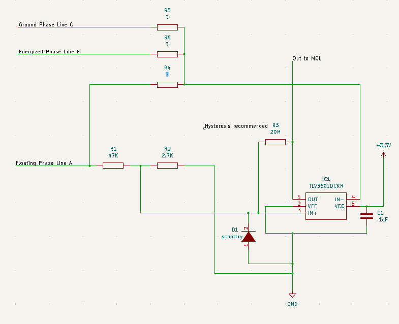
For the virtual neutral resistor network (R4, R5, R6), I am unsure what resistor values to use. I do not understand what the voltage of the neutral point is supposed to be or what we are comparing. The comparator is of course limited to 6 V, so it must be scaled down. I have read that the floating voltage or back-EMF is half the bus voltage. So if my battery is 52 V and at max. load, the floating phase can reach +/-26 V? Seems so high. So I just use a divider to scale that down I assume; I have 47 kΩ and 2.7 kΩ (R1/R2) which would be about 1.4 V at half the bus voltage under max. load. For sake of simplicity, if I sample the floating phase line and read a voltage of 1.4 V, then I can safely assume the winding and rotor are aligned and to energize the next step. But that would be slow on the MCU side, hence why we use comparators I suppose.

So if the floating phase line voltage > the neutral point voltage then the comparator will output HIGH. Turn off the PWM that drove the high-side MOSFET and immediately sample the output to detect the HIGH and then turn on the corresponding MOSFET. I assume we sample after PWM is off to avoid interference.

Also, the documentation for comparator recommends some hysteresis, is my resistor correct there? Just a light resistor from output to IN+.

enter image description here

\$\endgroup\$

1 Answer 1

3
\$\begingroup\$

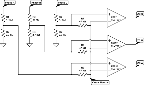
You need to scale down the virtual neutral point too. One way to do it is connect your summing resistors onto the voltage dividers (where the voltage has already been scaled down) like this:-

schematic

simulate this circuit – Schematic created using CircuitLab

The summing resistor values need to be large compared to the impedance of the dividers. 47 k || 2.7 k = 2.55 k which is 18 times smaller than 47 k, so the loading is negligible.

For this application you don't need 300 MHz comparators. Many comparators have hysterysis built in, but in any case you don't need it here because the software will filter out crossover noise.

The diode should not be necessary, because the scaled-down phase input should not go below ground.

\$\endgroup\$
5
  • \$\begingroup\$ Ok I think I understand the logic here a bit better. Just to be clear, the poles (+/-) should be flipped for CMP3, I assume it was just an error. So let us say Phase B is energized and C is grounded at full load (52v), then R3/R4 and R5/R6 will output 2.82v to CMP1 & 2. So then the virtual neutral would be further halved R9/R8 at 1.41v? So floating Phase A would generate half the bus (26v) and divided by R1/R2 = 1.412v compared to 1.41 virtual neutral? This might be wrong. I am trying to picture what volts we would compare at full 52v. \$\endgroup\$
    – vm1988
    Commented Jan 11, 2023 at 19:17
  • \$\begingroup\$ Yeah CMP3 really should be flipped. But hey, not a biggy. We'll just invert it in the software! (now corrected). At zero crossing point the other 2 phases are high and low respectively, so the neutral voltage (without back-emf) is indeed ~1.41V (ie. half the reduced supply voltage), right where you want it. \$\endgroup\$ Commented Jan 11, 2023 at 20:56
  • \$\begingroup\$ haha Thank you Bruce, I appreciate the help on this. I really enjoy learning this btw. Ok so that all makes sense for the zero crossing...but then when my floating phase comes to the winding and "generates" some emf...what is that voltage when divided by R1/R2? I read that the back-emf is half the bus also but in opposite polarity. So when I sample CMP3 will it be high or low? So 1.41v on negative vs X on the positive. \$\endgroup\$
    – vm1988
    Commented Jan 11, 2023 at 21:28
  • \$\begingroup\$ The generated back-emf will shift the neutral point, but this doesn't matter because there is still a voltage difference between it and the phase. At the point you are interested in (zero crossing) back-emf is zero and the neutral point voltage is correct. \$\endgroup\$ Commented Jan 11, 2023 at 21:36
  • \$\begingroup\$ Ahh ok excellent. Ok perfect I am going to update my PCB! Thank you Bruce this answers my confusion. \$\endgroup\$
    – vm1988
    Commented Jan 11, 2023 at 21:41

Your Answer

By clicking “Post Your Answer”, you agree to our terms of service and acknowledge you have read our privacy policy.

Not the answer you're looking for? Browse other questions tagged or ask your own question.