3
\$\begingroup\$

I made a DC-DC step up (boost) converter and when I use a 68 μH inductor, my circuit can supply some current (the 90 mA I need), and works as I expect it to. I used a 150 Ω resistor as a load to draw current. This is my hookup:

schematic

simulate this circuit – Schematic created using CircuitLab

AP3012KTR-G1

BAS516,H3F

L1 is 7447720680

(I used 3 diodes to reduce the total Vdrop on them. I also used fast switching diodes, but they are just for test purposes.)

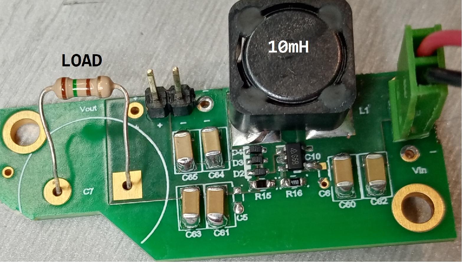
Then, I changed the inductor L1 and used an SRR1280-103K 10 mH inductor just to see what would happen. I get the 7 V output with no load, but if I add a load and try to draw the 90 mA of current that I need, the inductor starts getting hot and the output voltage below 7 V (1 or 4 V maybe, I stopped powering it once I saw it was getting slowly hot and did not measure it again to be sure,) and the boost circuit draws about ~300 mA (I can see that current draw from my bench power supply.) These 300 mA do not go to my load since the output of the boost converter does not give 7 V anymore, so it is consumed by the IC, through the inductor (as I understand.)

boost step up

I put back my 68 μH inductor to make sure this was the issue and indeed. When I used the 68 μH inductor, I could again draw my 90 mA.

My questions:

  • Why does using a larger value inductor not let me draw more current? Is it because of the value of the inductance, or because of other characteristics/properties of the inductor like its resistance or self resonance frequency? A larger inductor typically has higher resistance and self-resonant frequency as I know.

  • When I try to draw my 90 mA on the load using the 10 mH inductor and I see my bench power supply drawing ~300 mA, where do these 300 mA go? The inductor gets hot so I suppose they flow through the inductor, and through the AP301KTR-G1 IC.

\$\endgroup\$
7
  • \$\begingroup\$ Have you simulated your circuit? What's the peak current limit of the IC? "I used 3 diodes to reduce the total Vdrop on them. I also used fast switching diodes" Silicon or Schottky? \$\endgroup\$
    – winny
    Commented Feb 1, 2023 at 15:58
  • \$\begingroup\$ @winny I have not simulated it no. The switching max limit of the IC is 500mA. The diodes are silicon ones. \$\endgroup\$ Commented Feb 1, 2023 at 16:01
  • 3
    \$\begingroup\$ EE 101 - simulate your circuit. No point in parallel silicon diodes as the hottest one will take all the current. If you want to minimize diode losses, use Schottkys. Datasheet is vague on OCP. Self resonant frequency on your 10 mH inductor is 2.52 MHz and your switching frequency is 1.5 MHz. Please probe SW pin. \$\endgroup\$
    – winny
    Commented Feb 1, 2023 at 16:11
  • \$\begingroup\$ @ChristianidisVasileios try low frequency . \$\endgroup\$
    – user140351
    Commented Feb 1, 2023 at 16:32
  • \$\begingroup\$ @winny not no point, but the advantage is incremental at best, and more significant at high power levels; there is indeed very little point at these low currents. \$\endgroup\$ Commented Feb 2, 2023 at 3:24

3 Answers 3

7
\$\begingroup\$

Why using a larger value inductor does not let me draw more current?

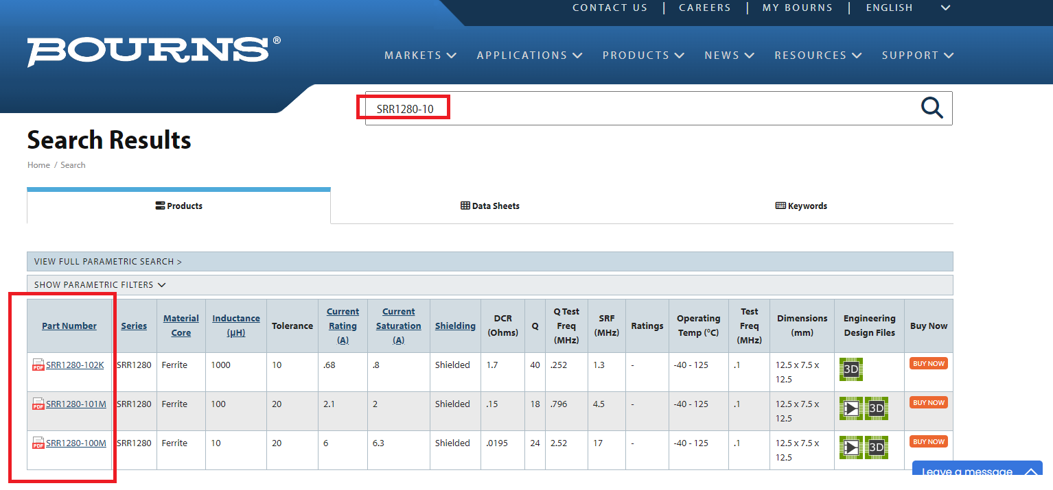
Because it has too much series resistance (losses) and you are linking the incorrect data sheet. In fact, it may be that Mouser and Digi-Key are both also linking the incorrect data sheet!! The SRR1280-102k (1 mH) has a DC resistance of 1.7 ohms so, I expect that the 10 mH inductor might be several times this DC resistance making it wholly unsuitable as an inductor for your job.

However, it seems like Bourns don't make this part at all: -

enter image description here

Anyway, the 1 mH part would struggle to work due to its high resistance so, the 10 mH part (if it existed from Bourns) is unlikely to work.

The basic problem is too much series resistance.


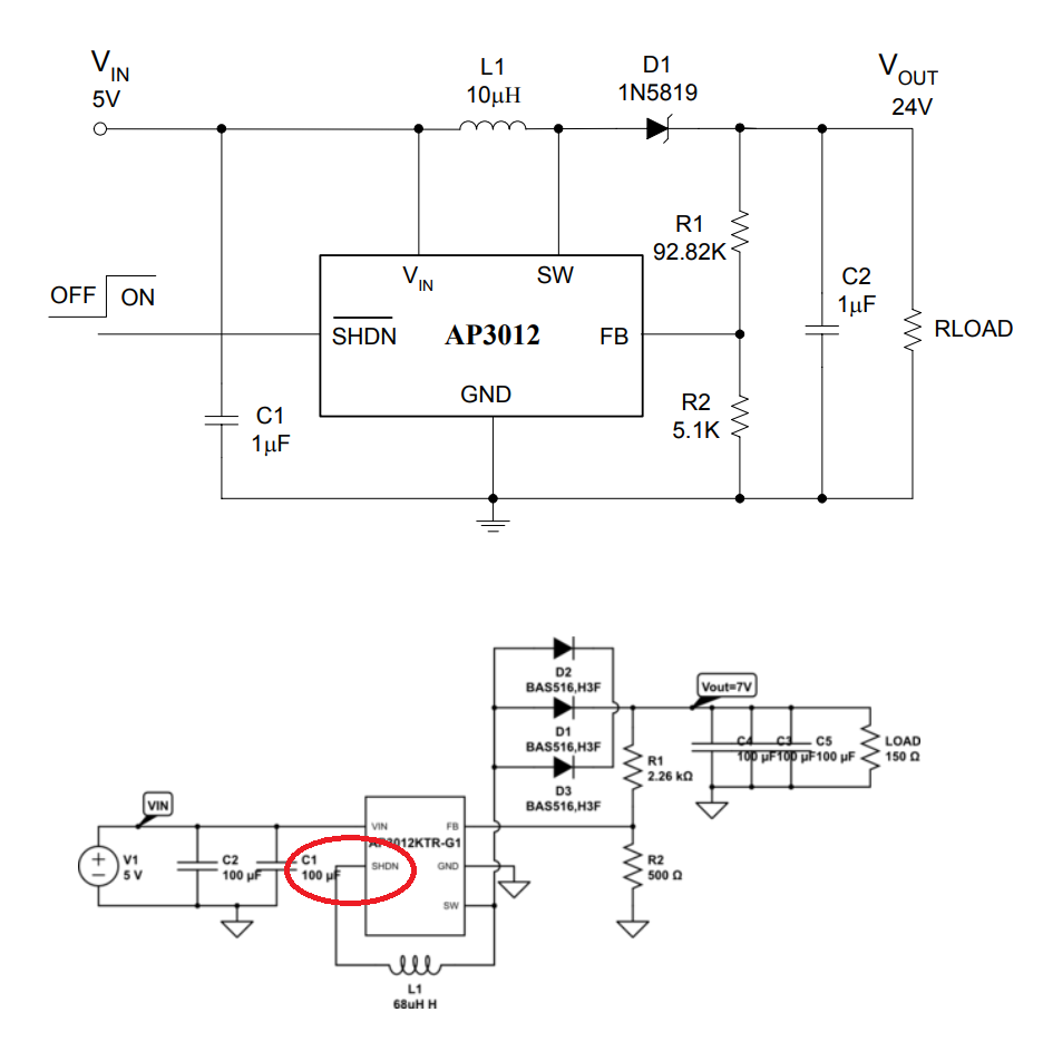
You should also not connect the inductor as you have: -

enter image description here

It needs to connect to the positive incoming supply and not \$\overline{SHDN}\$. You have also misconnected two of the paralleled diodes.

\$\endgroup\$
6
  • \$\begingroup\$ Oh I did the schematic wrong in the question, I have actually connected the inductor between SHDN and SW. I have also shorted VIN and SHDN. I am editing my question... \$\endgroup\$ Commented Feb 2, 2023 at 9:23
  • \$\begingroup\$ If you edit your question to correct your mistake then you'll invalidate my answer @ChristianidisVasileios so, best leave alone unless you make it crystal clear why you are editing. \$\endgroup\$
    – Andy aka
    Commented Feb 2, 2023 at 9:27
  • \$\begingroup\$ Okay I will just add a comment to my question and wont edit it. \$\endgroup\$ Commented Feb 2, 2023 at 9:28
  • 1
    \$\begingroup\$ You don't really need to change your question at all. Why move the goalposts when there are three answers already? \$\endgroup\$
    – Andy aka
    Commented Feb 2, 2023 at 9:30
  • 1
    \$\begingroup\$ It was no problem reading it in its original state. \$\endgroup\$
    – Andy aka
    Commented Feb 2, 2023 at 9:37
5
\$\begingroup\$

tl; dr: the excess power is being shed as heat in the inductor, in the malfunctioning chip and in the silicon (non-Schottky) diodes. Change your design to follow the datasheet reference.

A DCDC’s inductor should be chosen so that it has about 30% ripple current at max load. The factors that influence this include the switching frequency and max current. Generally, the lower the frequency, the bigger the inductor.

Lower currents can allow using bigger inductors to reduce the ripple relative to the average current. But not 100-1000x as big. The I^R (resistive) and hysteretic losses will be immense.

Also, there may not be enough residual ripple for the device to operate properly (the AP3012 is a current-mode device so it needs to see some ripple), and the device will not achieve stable operation due to its control loop being out of whack with such a mis-specified inductor.

What to do? The data sheet gives guidance for inductor selection. Diodes recommends 10uH. That’s reasonable for a device with a 1.5MHz switching frequency. Even 68uH is too big.

If your goal is max current, if anything you should be trying to make the inductor smaller in value, with a correspondingly lower DC resistance, or choose a physically larger inductor at that value with a lower DCR. That said, a 10uH 2520 size (like this one) is just fine for this part. You could even go 2020 or 2016.

Also, you’re wasting your money with the multiple (and wrong) diodes. Not only will they not reduce your losses, but you've chosen a silicon type which has a higher Vf. Just choose one 1A Schottky type. They recommend a 1N5819, that’s perfectly fine. The BAS516 you chose is not Schottky, so will reduce efficiency due to its higher forward drop.

As for a deeper understanding of the inductor selection, the BCD/Diodes datasheet is very thin on details. TI has an appnote for boost inductor selection. Link: https://www.ti.com/lit/an/slva797/slva797.pdf

I’m not necessarily recommending TI over Diodes. Rather, the design procedure given in the TI appnote would apply to the Diodes part too.

\$\endgroup\$
4
\$\begingroup\$

Why using a larger value inductor does not let me draw more current?

Because of a misunderstanding. To increase the current capacity - assuming the rest of the circuit can handle it - you need a physically bigger inductor, not one with a larger inductance. An inductor with bigger dimensions but same inductance will typically have lower losses and higher average and peak current capacities. You need more core material and windings with larger cross-section. That takes bigger volume, everything else being the same.

There's no connection between inductance and load current as you imply. As long as the inductor can support the peak current and average current, it does its job. If the other parts of the current loop can sustain this, you're set. Increasing the inductance further will only decrease the ripple amplitude - eventually to a point where some switching converters will be unable to regulate. That's because they (not all) depend on the presence of ripple current to control switching. The average current will remain the same, and that's what dictates the output current.

When I try to draw my 90 mA on the load using the 10 mH inductor, and I see my bench power supply drawing ~300 mA, where do these 300 mA go?

The current flows through the inductor and ohmically heats it up. The current is high since the switcher does its best to try and regulate the output voltage, so it keeps driving the inductor hard, heating it up. The regulation doesn't happen because the inductor converts most of the energy into heat and not into magnetic field energy. It's a big inductor, but due to a much higher inductance it's also much less efficient at a given current - potentially it may even be saturating, turning into an air-core inductor at times, with inductance way too low.

Generally speaking, to increase the current capacity of a boost converter, without changing topology, you need parts that can sustain higher current: be it the switching element, the diodes, the capacitors, the inductor. All of this has to be designed together.


What output voltage do you need and at what current? We can then look at a complete design that would work for that.

\$\endgroup\$
1
  • \$\begingroup\$ I wont need further help. Thank you all :) \$\endgroup\$ Commented Feb 2, 2023 at 9:31

Your Answer

By clicking “Post Your Answer”, you agree to our terms of service and acknowledge you have read our privacy policy.

Not the answer you're looking for? Browse other questions tagged or ask your own question.