0
\$\begingroup\$

I want to make a trigger for my project. I saw this PCB for triggering the RF part of the PCB. I think one PCB has an IR receiver and the other part has an IR transmitter so they can trigger the RF part at some point.

They say this PCB is an IR receiver module but I think D2 is an IR LED. Am I wrong? Could D2 be an IR receiver, and D1 an IR LED?

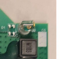
enter image description here

\$\endgroup\$
3
  • 2
    \$\begingroup\$ Difficult to say. Clear tends to be LED since if its IR the receiver tends to be black to filter out visible light. You could clip a voltmeter to the leads and wave your hand in front of it in the sun. If you get a significant change it's a receiver. If only a small change it's an LED \$\endgroup\$
    – DKNguyen
    Commented Feb 10, 2023 at 15:27
  • \$\begingroup\$ Even more unclear as LEDs can be used as (ineffective) photodiode as well. You told very little about what devices you have! \$\endgroup\$
    – datenheim
    Commented Feb 10, 2023 at 15:53
  • 1
    \$\begingroup\$ Can you take a better photo? \$\endgroup\$
    – LarryBud
    Commented Feb 10, 2023 at 16:19

1 Answer 1

0
\$\begingroup\$

You could find out by desoldering the "led" and in combination of a suitable resistor connect it to a power supply and see if it emits light, you can probably detect with a camera. Don't forget their rotation, mark it with a dot.

Like a commenter said, optical diodes are black. Also leds generate power of you focus light on it and measure it with a multi meter.

\$\endgroup\$

Your Answer

By clicking “Post Your Answer”, you agree to our terms of service and acknowledge you have read our privacy policy.

Not the answer you're looking for? Browse other questions tagged or ask your own question.