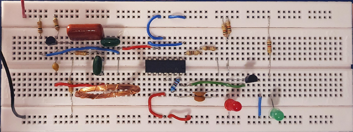
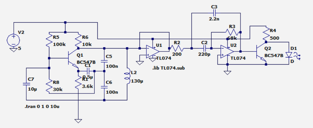
I'm building a simple metal detector. There is a Colpitts oscillator with a confirmed (measured on CRO and simulated) frequency of 62 kHz. I now need to take this base frequency and detect changes, which indicates the presence of a metal nearby. When a metal is near, the inductance increases and the frequency drops.
I've used a voltage follower to buffer the output of the oscillator. Then fed this buffered output into an infinite gain multiple feedback active bandpass filter using a TL074CN op-amp. Datasheet Link
The intent was, the base frequency would be output by the op-amp which would switch on a BJT that would short-circuit an LED. If the frequency changes, the op-amp output would drop, switch off the BJT, and the LED will switch on as the current into the collector will go through the LED into the ground.
The bandpass filter designed values are centre frequency 62 kHz with a bandwidth of approx 7 kHz, quality factor of 9, and gain is 170.
Neither the LTSpice simulation nor the built model seems to work. The simulation output is flat at 1.5 V.
The breadboard model doesn't work either, it seems the voltage output of the filter is too high it consistently switches on the BJT. Removing the base wire confirms that the BJT and LED are all working. I've tried with a 3 V and a 9 V supply.
Edit
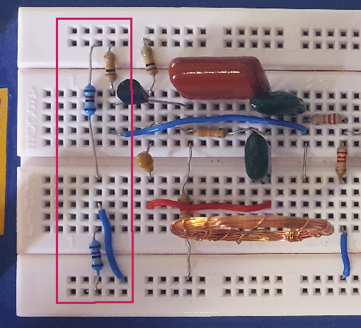
I've redesigned it to take a 9V battery, so +/-4.5 V rails. To do this, I used two 68k Ohm resistors for a voltage divider, with a wire connecting to the ground rail connected to the node in between them. However I am now not getting any power delivered to the components. The battery and all other components (LEDs, op-amps, BJTs) work when the negative terminal is connected to the ground. I have an ON indicator LED that simply switches on when there is a power supply which should not be affected by the rest of the circuit yet it still is not switching on.
The voltage divider resistors and wire are encircled.


