To begin
Two equivalent forms of the low-pass standard form term (three terms are possible for the full 2nd order TF):
$$\begin{align*}
\frac{V_{_\text{OUT}}}{V_{_\text{IN}}}&= A_0\cdot\left\{\begin{array}{l}
\frac1{
\left(\frac{s}{\omega_{_0}}\right)^2+\frac1{Q}
\left(\frac{s}{\omega_{_0}}\right)+1}
\\\\
\frac{\omega_{_0}^2}{s^2+2\zeta\:
\omega_{_0}s+\omega_{_0}^2}
\end{array}\right.
\end{align*}$$
(I use \$A_0\$ for the gain and not \$H\$, with the 0 implying the low-pass gain. A full 2nd order transfer function may also have \$A_2\$ and \$A_1\$ for the high-pass and band-pass terms.)
This configuration
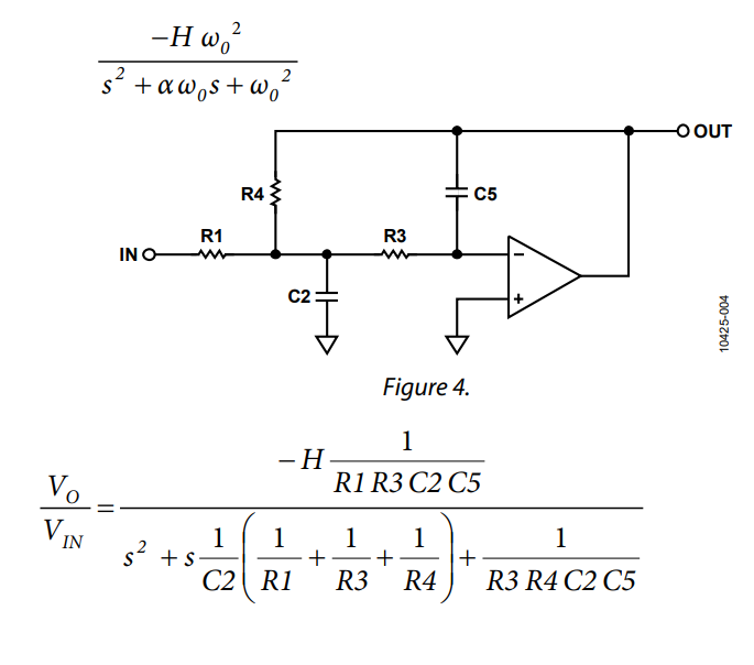
The multifeedback solution for your schematic is:
$$\begin{align*}A_0&=-\frac{R_4}{R_1}\\\\\omega_{_0}&=\frac1{\sqrt{R_3\,R_4\,C_2\,C_5}}\\\\\zeta&=\frac12\cdot\sqrt{\frac{C_5}{C_2}}\cdot\frac{\sqrt{R_3\,R_4}}{R_1\,\mid\mid\, R_3\,\mid \mid\, R_4}, \text{ or:}&Q&=\sqrt{\frac{C_2}{C_5}}\cdot\frac{R_1\,\mid\mid\, R_3\,\mid \mid\, R_4}{\sqrt{R_3\,R_4}}\end{align*}$$
Sanity check
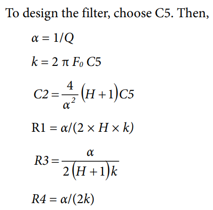
The form they used is closer to the \$\zeta\$-form, so I'd start with \$2\zeta\,\omega_{_0}=\frac1{C_2}\left(\frac1{R_1}+\frac1{R_3}+\frac1{R_4}\right)\$. Since \$2\pi \,f_{_0}=\omega_{_0}\$ then their \$k=\omega_{_0}\cdot C_5\$. Also, their \$\alpha=2\zeta\$.
So let's start at the beginning and just plug things in for a sanity test:
$$\begin{align*}
2\zeta\,\omega_{_0}&=\frac1{C_2}\left(\frac1{R_1}+\frac1{R_3}+\frac1{R_4}\right)
\\\\&=
\frac1{\frac4{\alpha^2}\left(1+H\right)C_5}\left(\frac1{\frac{\alpha}{2 \,H\, k}}+\frac1{\frac{\alpha}{2\,\left(1+H\right)\,k}}+\frac1{\frac{\alpha}{2\,k}}\right)
\\\\&=
\frac{\alpha^2}{4\left(1+H\right)C_5}\left(\vphantom{\frac1{\frac{\alpha}{2 \,H\, k}}}2 \,H+2\,\left(1+H\right)+2\right)\frac{k}{\alpha}
\\\\&=
\frac{\alpha^2}{4\left(1+H\right)C_5}\left(\vphantom{\frac1{\frac{\alpha}{2 \,H\, k}}}4 \,H+4\right)\frac{k}{\alpha}
\\\\&=
\frac{\alpha\,k}{C_5}
\\\\&=
\frac{\left(2\zeta\right)\,\left(\omega_{_0}\,C_5\right)}{C_5}
\\\\&=
2\zeta\,\omega_{_0}\end{align*}$$
So their algorithm checks out. Someone sane was involved. Good.
Understanding their algorithm
Now let's see how it might have been developed in the first place.
If we are given \$C_5\$, then it follows that \$\frac1{C_2}=R_3\,R_4\,C_5\,\omega_{_0}^2\$. So, using the definition for \$\omega_{_0}\$ we can find that:
$$\begin{align*}
2\zeta\,\omega_{_0}&= \frac1{C_2}\left(\frac1{R_1}+\frac1{R_3}+\frac1{R_4}\right)\\\\
2\zeta\,\omega_{_0}&=R_3\,R_4\,C_5\,\omega_{_0}^2\left(\frac1{R_1}+\frac1{R_3}+\frac1{R_4}\right)\\\\
2\zeta&=R_3\,R_4\,C_5\,\omega_{_0}\left(\frac1{R_1}+\frac1{R_3}+\frac1{R_4}\right)\\\\
\frac{2\zeta}{\omega_{_0}\,C_5}&=R_3\,R_4\left(\frac1{R_1}+\frac1{R_3}+\frac1{R_4}\right)\\\\
\frac{\zeta}{\omega_{_0}\,C_5}&=\frac12 R_3\,R_4\left(\frac1{R_1}+\frac1{R_3}+\frac1{R_4}\right) \\\\
\text{Clearly, }\frac{\zeta}{\omega_{_0}\,C_5}&\text{ is a resistance -- substitute in the gain, now}\\\\&=\frac12 R_3\left(\frac{R_4}{R_1}+\frac{R_4}{R_3}+1\right)\\\\
&=\frac12 R_3\left(H+1+\frac{R_4}{R_3}\right)\\\\\text{To resolve }&\frac{R_4}{R_3},\text{ assign }R_4=\frac{\zeta}{\omega_{_0}\,C_5}\text{ and place it on the left side}\\\\
R_4&=\frac12 R_3\left(H+1+\frac{R_4}{R_3}\right)\\\\
\frac{R_4}{R_3}&=\frac12 \left(H+1+\frac{R_4}{R_3}\right)\\\\
\text{Then assign }&u\text{ as the ratio }\frac{R_4}{R_3}\text{ and solve}\\\\
u &= \frac12 \left(H+1+u\right)\\\\
2 u &= H+1+u\\\\
u &= H+1
\end{align*}$$
Given the definition \$R_4=\frac{\zeta}{\omega_{_0}\,C_5}=\frac1{2 Q\,\omega_{_0}\,C_5}\$ and from the gain \$\mid A_{_0}\!\mid=H=\frac{R_4}{R_1}\$ requiring \$R_1=\frac1{H}R_4\$, it follows that remaining conditions then require \$R_3=\frac1{H+1}R_4\$.
So the resistors are done. (All this started out given \$Q\$, \$\omega_{_0}\$, and \$C_5\$. Nice.)
Now for \$C_2\$.
(I'm taking short-cuts, now, instead of writing out lists of tiny incremental steps I'm sure you can handle from here out.)
Return to \$2\zeta\,\omega_{_0}=\frac1{C_2}\left(\frac1{R_1}+\frac1{R_3}+\frac1{R_4}\right)\$. With the new resistor values, this becomes \$2\zeta\,\omega_{_0}=\frac1{C_2}\cdot 2\left(H+1\right)\cdot\frac{\omega_{_0}\,C_5}{\zeta}\$.
Solving, and canceling stuff out, find that \$C_2=\frac{H+1}{\zeta^2}C_5\$.
Substituting in \$\zeta=\frac1{2\,Q}\$, this works out to \$C_2=4 Q^2\left(H+1\right)\,C_5\$.
Summary
They chose to set up their own variables. For example, assigning \$\alpha=\frac1{Q}\$, which makes \$C_2=\frac{4}{\alpha^2} \left(H+1\right)\,C_5\$. Just as they wrote in your question. (I would not have bothered to define \$\alpha\$. It's not needed here and it is less confusing to just use \$Q\$.) But it will all work out the same, when all is said and done.
$$\begin{align*}
C_2&=4 Q^2\left(H+1\right)\,C_5\\\\
R_4&=\frac1{2 Q\,\omega_{_0}\,C_5}\\\\
R_1&=\frac1{H} \,R_4\\\\
R_3&=\frac1{H+1}\,R_4
\end{align*}$$
(Don't forget \$C_2\$ and \$R_4\$ may be multiplied together to get a \$\tau=C_2\,R_4=\frac{H+1}{\zeta\,\omega_{_0}}\$. So the new form of the denominator term, \$\frac1{C_2\,R_4}\left[2\left(H+1\right)\right]s\$, expands to \$2\zeta\,\omega_{_0}s\$. As must be.)


