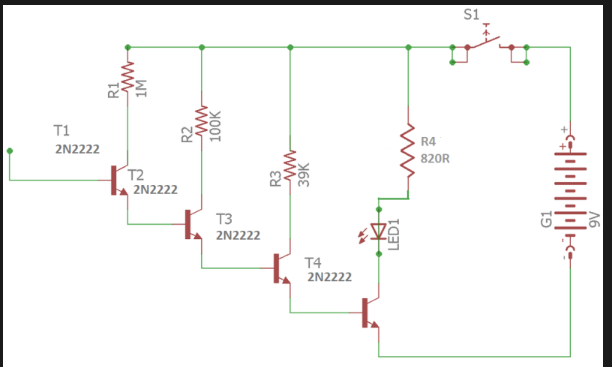
I found the following circuit online (source linked below). It apparently amplifies ambient EMF signals (like those generated from power lines) using an antenna at the base of T1.
I recall learning in my microelectronics class that for a transistor to operate as an AC signal amplifier, it must have a DC operating point (Q point) set. For this to occur, a +0.7V difference across the base-emitter junction must exist (for NPN). How is that achieved in this circuit for the input transistor (T1) with just an antenna?
2 Answers
T1 is not being used as a linear amplifier so a DC bias is not necessary. The open T1 base (antenna) will pick up AC noise and conduct a very small current on each positive noise pulse. The remaining transistors increase the pulsing current until on the last transistor an LED can be driven.
I recall learning in my microelectronics class that for a transistor to operate as an AC signal amplifier, it must have a DC operating point (Q point) set. For this to occur, a +0.7V difference across the base-emitter junction must exist (for NPN). How is that achieved in this circuit for the input transistor (T1) with just an antenna?
There is a common rule of thumb that base-emitter voltage of a Silicon NPN is 0.7 V when the base-emitter junction is conducting, this is only an approximation. A more accurate mathematical relationship between the voltage across a base-emitter junction and the current through the base is the Shockley Diode Equation
$$I_b = I_S\left(e^{\frac{V_{be}}{V_T}}-1\right)$$
where \$I_S\$ is the reverse saturation current, sometimes called the scaling current, and \$V_T\$ is the thermal voltage, which is about 26 mV at room temperature.
From this equation, one can see that, even though \$I_b\$ can be quite small when \$V_{be}\$ is small, \$I_b\$ is nevertheless not 0, unless \$V_{be}\$ is 0.
Note that the voltage at the base of the first transistor must be referenced to something else. It could be a metal case containing the circuit. It could be a human hand holding the circuit. It could just be another part of the circuit board. But there must be some capacitance to allow current to flow in and out of the base of the first transistor.
Because the electric field sensor circuit has 4 cascaded transistors, even though the signal present at the first transistor is very small indeed, by the time the signal leaves the 4th transistor, it is has been sufficiently amplified to light the LED.

