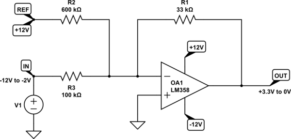
First of all, I'm pretty new in this area of electronic circuit design so I might end up saying something pretty dumb in the course of my question. Also, English is not my native language, so sorry for any mistakes. This is my very first question here too.
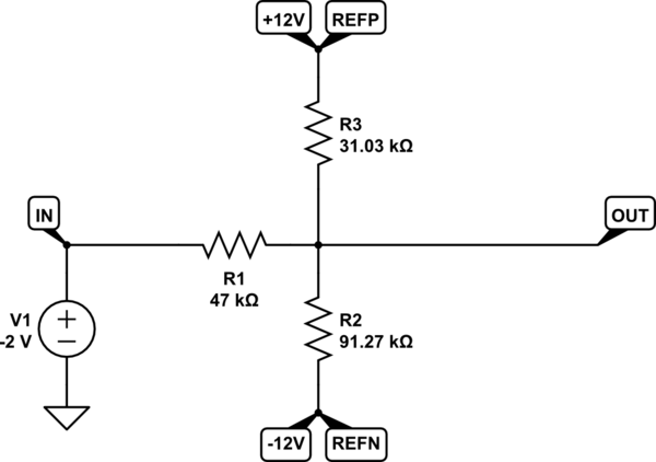
My problem is the following. I have a pressure sensor that is powered with 24V and spits out a signal from 0V to 10V proportional do the pressure reading. The sensor has three wires: +24V, GND and SIGNAL. The microcontroller I use to read this signal is a 3.3V based one, so I needed some voltage divider to do this conversion.
For some reasons this voltage divider circuit needs to be buffered, so I used an OpAmp. Since there are other circuits in this same board that uses OpAmp's that need symmetrical power and I need the OpAmp for the voltage divider to be able to reach 0V, I used a TLE2426 rail splitter to generate a +12V/-12V for the board (I must use a 24V power supply to power this board).
I need to connect the GND of the microcontroller to the virtual GND of the TLE2426. The problem is that the reference from wich I'll be measuring the output of the voltage divider circuit is the virtual GND generated by the TLE2426, and the reference from wich the sensor will output its signal is the GND from the 24V power supply. I know I can't connect this two GND's together.
The circuit I have is as follows:

simulate this circuit – Schematic created using CircuitLab
Things i thought might solve the problem:
1 - Using the PS GND as the GDN for the voltage divider only. Will the OpAmp output the correct voltage to the virtual GND in this case?
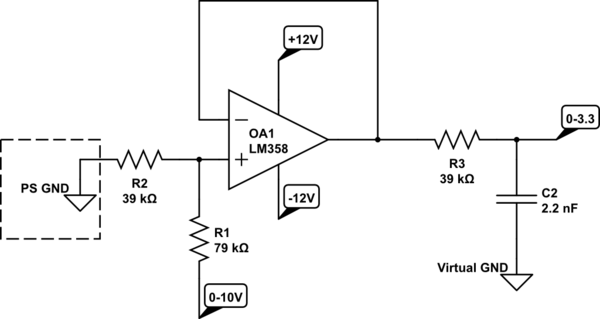
2 - Using a boost converter in the +12V and virtual GND lines to generate +24V again but with a common ground this time and then powering the sensors with this circuit. I don't know if I can use this type of circuit with a virtual GND or if this will generate some sort of noise in the circuit.
EDIT:
So, I continued searching about this subject and, changing some of my keywords, I found this other post here:
Inverting Buck-Boost -12V converter Schematics
Maybe this works out for me. I can use a LM7812 to generate a +12V and a LM2576 in the configuration shown in the post to generate the -12V and the GND of both input and output is the same which will solve my problem with the pressure sensors. What do you think?
EDIT 2:
Just to clarify: I need a negative suply voltage because in this same board I have a circuit that takes the 0V-3.3V from de MCU and converts it to -10V-+10V for the drive of an actuator I have. Since both circuits (the one that reads the pressure sensors data and the one that generate the signal for the actuator) are connected to the MCU I need to have the same GND for both.

