Despite what some op-amps claim, none that I am aware of are able to get their outputs all the way to their positive or negative supply potentials. Furthermore, op-amps all have a limited range of permissible input potentials, often very similar to their output range. In some cases, taking an input outside of that range can cause the output to fly off to the opposite extreme, a phenomenon called phase reversal.
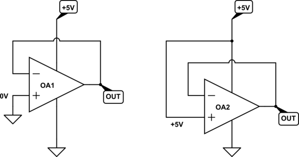
That means both of these situations are always problematic:

simulate this circuit – Schematic created using CircuitLab
You have to take care not to exceed the limits imposed at the inputs, or expect an output swing extending to either supply. You applied 0V to the non-inverting input, and were surprised to find that the output was above zero, by some 40mV. Now you know why.
The obvious solution, but one that is quite inconvenient, is to provide the op-amp with a negative supply potential, for example \$V_{EE} = -5V\$. This solves two problems. Firstly, the inputs can now be taken all the way to 0V, and the output is able to follow, as expected.
Another inconvenient consequence of this solution is that the op-amp is now able to output negative potentials, which can be harmful to the subsequent ADC, and steps must be taken to protect it.
If you choose not to go that route, then have two issues to address. Firstly, an op-amp input of 0V may not be acceptable. Secondly, even it it were, the corresponding follower output of 0V is not even possible.
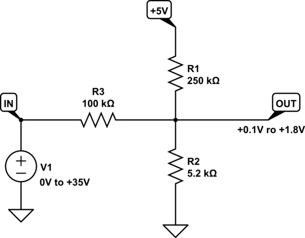
The simplest way I can think of to get past these hurdles, without having to obtain a negative supply somehow, is to raise the minimum op-amp input potential to 100mV or so. This would mean that 0V at your input would result in +100mV at the op-amp's non-inverting input, and an input of +35V would apply +1.8V.
Obviously, this means that you will lose some of the lower counts of the ADC, but that's still \$\frac{1.8V-0.1V}{1.8V} = 94\%\$ of full scale. This 100mV offset can be compensated for in software.
To introduce a +100mV offset will require some modification to the potential divider, and some algebra to figure out the resistor values. You will require a low impedance, low noise, stable positive reference potential. If you trust your op-amp's positive supply in these respects then you can use that:

simulate this circuit
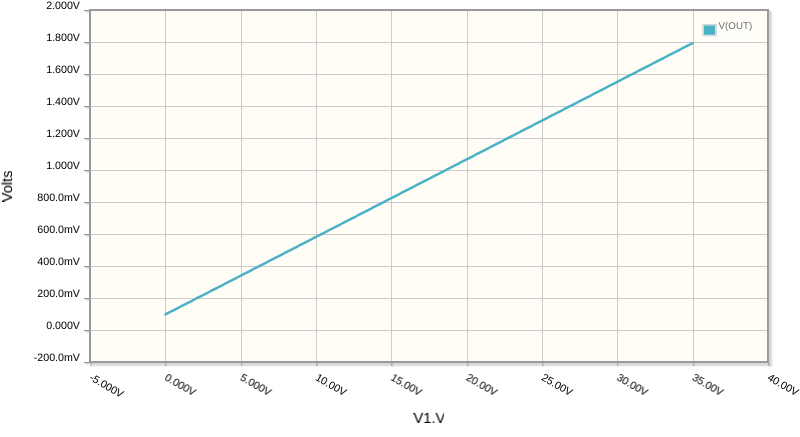
That circuit yields the relationship between input and output you are looking for, as shown in this sweep of input from 0V to +35V:

Your ADC has 12 bits of resolution, which is \$2^{12}=4096\$ distinct values, each representing \$\frac{1.8V}{4096}= 440\mu V\$. Power supply fluctuations will find their way to OUT, attenuated by a factor of \$\frac{R_2}{R_1+R_2}=\frac{1}{20}\$. That means 1 bit corresponds to \$20 \times 440\mu V = 9mV \$ of ripple in the +5V supply.
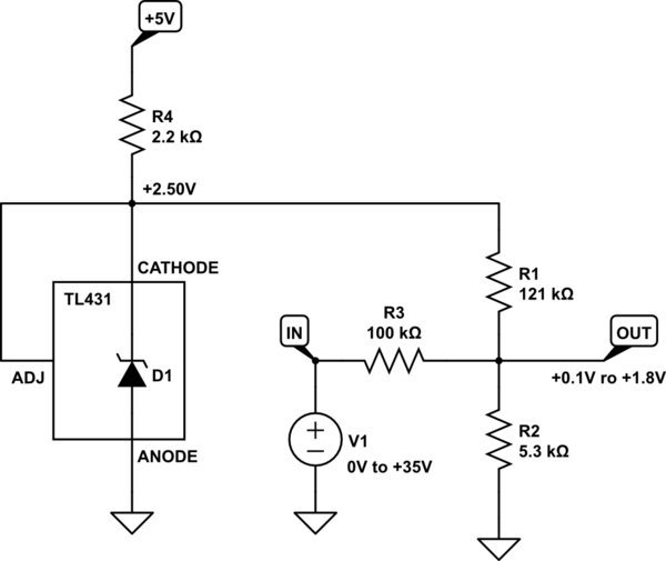
If your supply has more ripple or variation than this, and you wish to retain the full 12 bits of accuracy, then you'll have to use a precision reference, such as the TL431:

simulate this circuit


