0
\$\begingroup\$

I am using the following circuit which receives a DC voltage from a transformed and filter capacitors. I am getting a problem of the voltage changes.

enter image description here

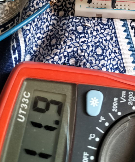
Here without load the potentiometer input coming from the regulator is practically giving:

enter image description here

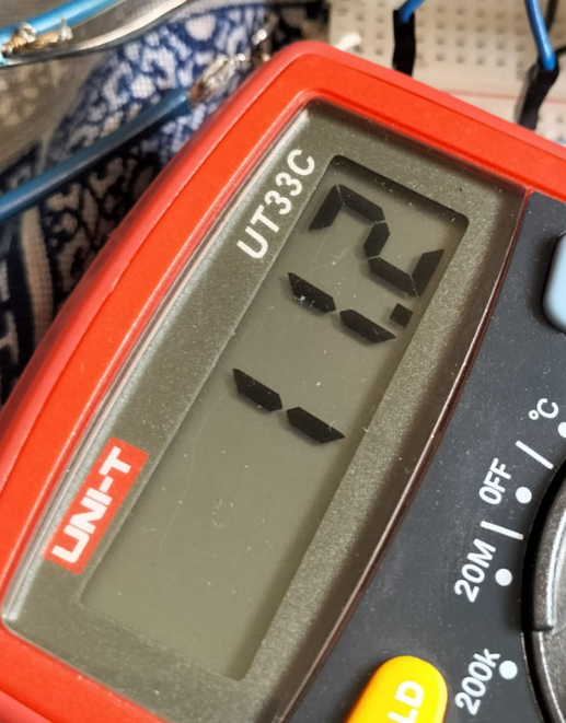
Without load the voltage I am getting across the load is:

enter image description here

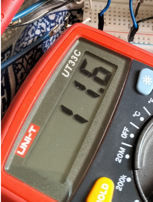
With load the input voltage to the potentiometer becomes:

enter image description here

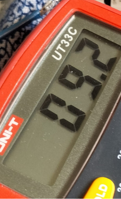
This input voltage change is not that much but this has resulted in a large change of 2 V in the output which is 9.2 V.

enter image description here

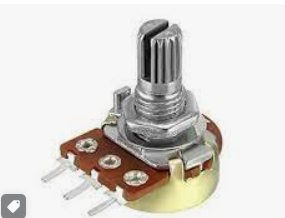
I haven't changed the knob of the potentiometer and I have received an unusual change. What can be the reason. I have used the potentiometer shown below:

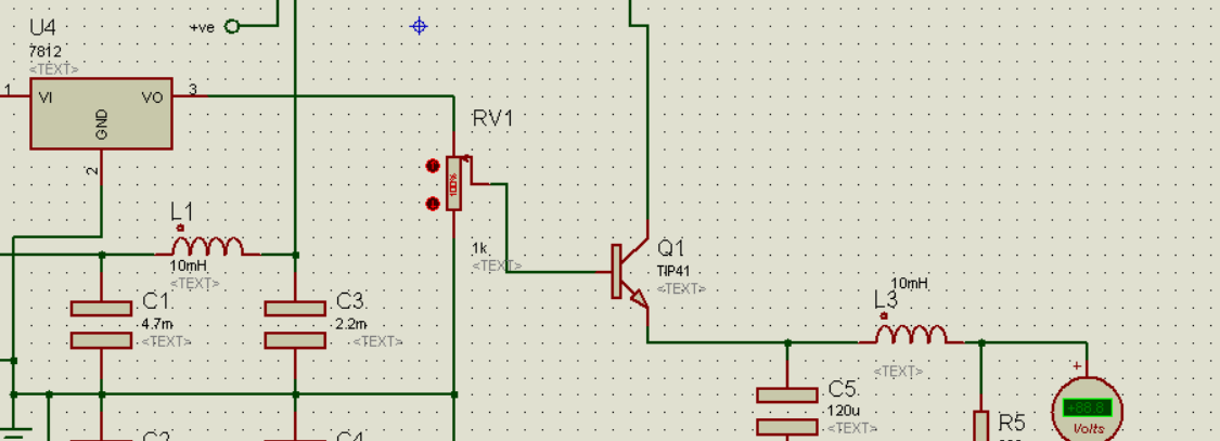
enter image description here

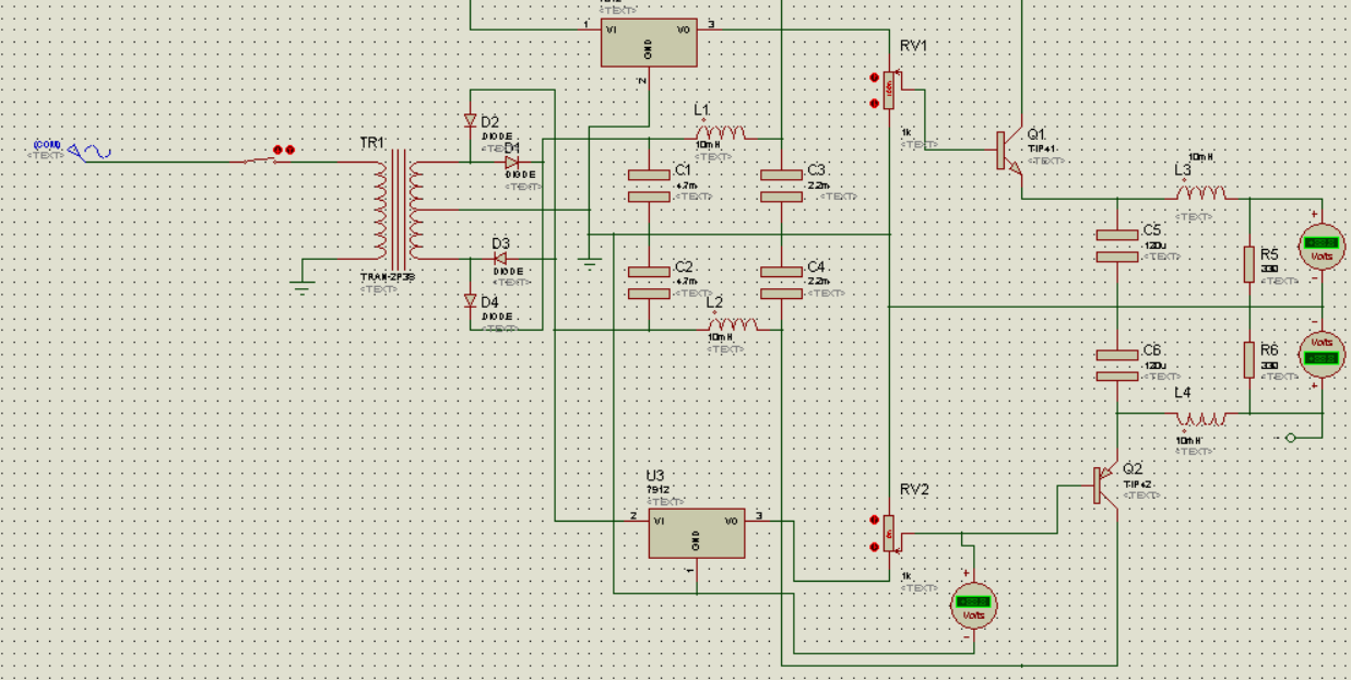
This is the complete schematic: enter image description here

\$\endgroup\$
12
  • \$\begingroup\$ What is the load resistance? What is the resistance of the 10 mH inductor? \$\endgroup\$ Commented Jun 18, 2023 at 5:11
  • 1
    \$\begingroup\$ A real inductor has resistance. I'm assuming you are building this with real parts? \$\endgroup\$ Commented Jun 18, 2023 at 5:41
  • 1
    \$\begingroup\$ Is the transformer primary connected to mains? If so, it's dangerous to connect Earth to the transformer primary. Shouldn't the primary be connected between live and neutral? With the primary between live and earth like that, the secondary is unlikely to provide the voltage you expect. And if ever that earth connection breaks, your entire circuit becomes live. \$\endgroup\$ Commented Jun 18, 2023 at 7:25
  • 2
    \$\begingroup\$ Does this answer your question? Voltage fluctuations in TIP122 \$\endgroup\$
    – winny
    Commented Jun 18, 2023 at 7:28
  • 2
    \$\begingroup\$ @EEK21 According to your schematic, mains-side ground and secondary side ground are the same node. That could end badly, unless your 120V/220V source is isolated from the REAL mains somehow. \$\endgroup\$ Commented Jun 18, 2023 at 8:37

1 Answer 1

1
\$\begingroup\$

You got some good answers to a very similar question a few days ago, but you appear not to have understood and have not implemented the design changes required.

It would be very helpful if you would draw a schematic using CircuitLab or LTspice, so you can run simulations and see the effects of various component changes and design modifications. If you are making an actual breadboard, there may be some problems due to grounding and poor connections, especially if you are running more than a couple amps.

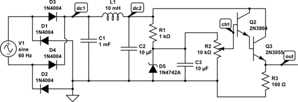
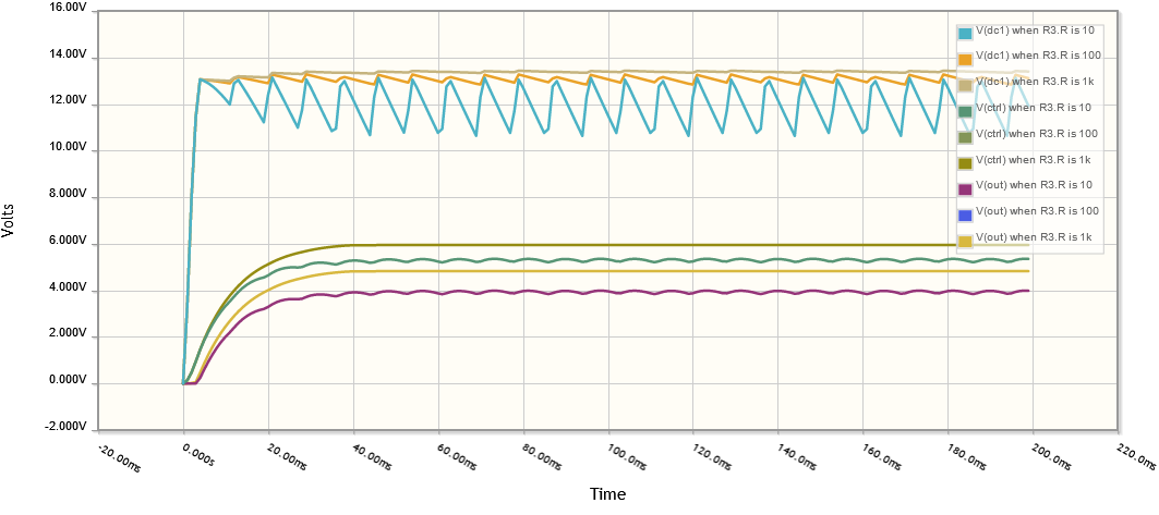
Here is a simple implementation of a variable 0-12 V power supply, set to 6 V, showing raw DC voltages for loads of 10, 100, and 1k, and control and output voltages for 10 and 1k loads.

schematic

simulate this circuit – Schematic created using CircuitLab

Power supply voltages

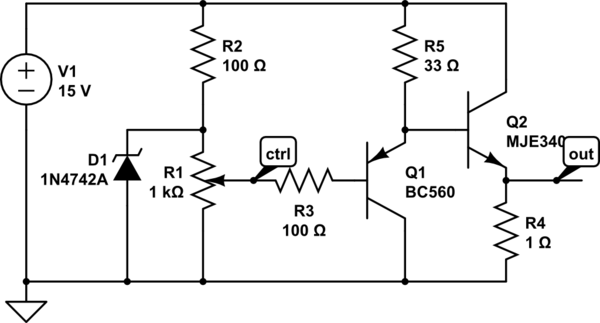
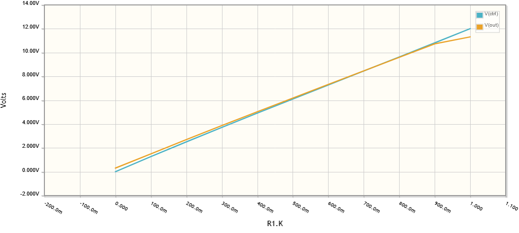
(edit) Here is a way to achieve nearly perfect correlation between a control signal and output:

schematic

simulate this circuit

Control and output voltages

\$\endgroup\$
2
  • \$\begingroup\$ I have done all the necessary changes mentioned in the last query. Didnt worked that's why am asking again. The simulation works fine on proteus. \$\endgroup\$
    – user340506
    Commented Jun 18, 2023 at 7:46
  • 1
    \$\begingroup\$ I'm not familiar with Proteus, but you should be able to do a parameter sweep, or several simulations, and show the voltages and waveforms as I have done. It's hard to read the values on your schematic. And you should show your entire breadboard. No need to post an image of the DMM, when just the numbers would be sufficient. \$\endgroup\$
    – PStechPaul
    Commented Jun 18, 2023 at 9:20

Your Answer

By clicking “Post Your Answer”, you agree to our terms of service and acknowledge you have read our privacy policy.