17
\$\begingroup\$

I understand that on circuit board traces with a clock, if the higher harmonics have sufficient power, it results in electromagnetic waves being emitted from the traces which creates EMI. What I don't understand is why this happens in the first place?

Why does a high frequency current have to pass through the conductor for it to emit EM radiation and why does this not happen with low frequency currents? What I understand is that the board trace is essentially starting to behave as an antenna in this case but I do not know the reason.

\$\endgroup\$

5 Answers 5

15
\$\begingroup\$

The follow-up question...

but what I don't understand is why the flow of electrons that are physical entities result in emission of these EM waves

Why does "radiation" occur?

Let's look at this specifically, because it is a common (and excellent) concern.

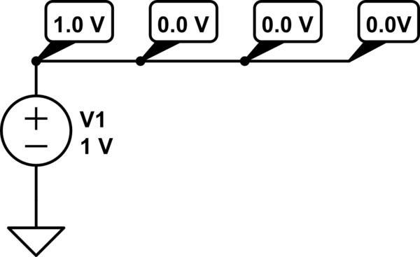
Here is a simple wire, instantly connected to a voltage source:
schematic

simulate this circuit – Schematic created using CircuitLab

At this moment in time, the potential difference between the left-end of the wire (adjacent to the source) and ground is 1 volt.

The extreme other end of the wire is still at ground (0 difference) because the electromotive force (voltage) of the source has not yet propagated to the other end of the wire.

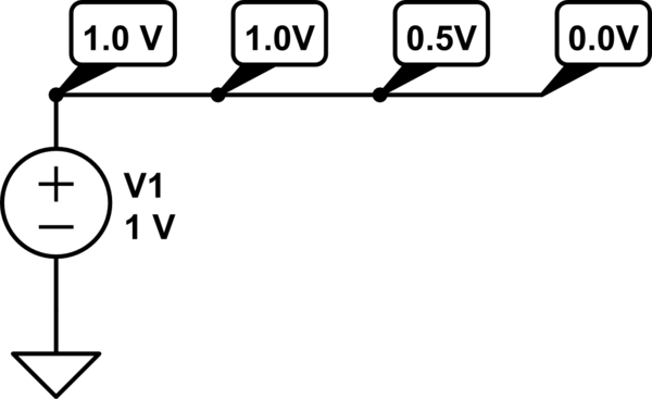
As time goes on, the voltage down the wire increases:
schematic

simulate this circuit

The electrons in the conductor are being accelerated by the electric field (the potential energy of the source being converted into kinetic energy in the electrons).

When the electrons reach the end*, they can't physically continue -- there's no more conductor to propagate along!

...but these charges have momentum in the direction of the wire (e.g. there is kinetic energy).

When the charges come to an abrupt stop at the end of the wire, the conservation of energy law requires that this energy must "go somewhere" -- it can't just disappear!

The answer is radiation. The energy leaves the end of the wire in the form of an electro-magnetic wave.

*It should be noted that the same electrons that start moving at one end of the wire are not necessarily the same electrons that reach the other end of the wire, but this isn't material to our discussion.

The fallout

A lot of neat things fall out of this. For example, you could think of the wire in our example as being composed of infinitely many smaller wires. For each of these, the same behavior would hold true (which is why radiation occurs down the entire length).

You can also see why radiation results from a change in the electro-magnetic field (e.g. from a change in current).

You can understand how linear antennas work. In our example, now imagine that just at the moment when the voltage peaks at the far end, we switch the source back to 0.0V. You would now have the identical picture but flipped over (1.0V on the right, 0.0V on the left) and the process would begin again.

Keep repeating this process and the electrons would be endlessly running back and forth (over the whole wire length) from one end to the other. That's a perfect linear antenna ("radiator").

If the wire were too short, there would be less movement and if too long, there would be too much. The voltage would keep increasing further down the wire as you reduce the voltage in the nearby section (interference results, which is hard to visualize with just these simple figures).

Now you can intuit trace behavior...

What I understand is that the board trace is essentially starting to behave as an antenna in this case but I do not know the reason.

At low frequencies (really, low edge-rates in "digital" circuits), the electrons have time to reach the end of the wire before the source is switched around and the electrons are asked to come back. This is called a "lumped element."

The voltage at each end of the wire is basically always the same. This is the behavior we teach to introductory electronics students (a wire is an equipotential surface = same voltage everywhere).

As the frequency increases, they have less and less time to make the trip and the voltage at each end of the wire can no longer be guaranteed to always be the same as shown in the previous figures.

In circuit board design, you don't need to worry much about radiation from lumped elements. A simple approximation is:

  1. Find the fastest rise-time (1/edge-rate) in your signaling = Tr
  2. Find the maximum frequency contained in this edge = f
  3. Keep tracks an order-of-magnitude shorter than the corresponding wavelength

That is:

$$f = \frac{1}{2T_r}$$

$$\lambda = \frac{c_m}{f}$$

$$l_{track} < \frac{\lambda}{10} = \frac{T_r c_m}{5}$$

where c_m is the speed of light in the medium (typically for a copper over FR-4 PCB c_m is approximately 1.5e8).

\$\endgroup\$
5
  • 4
    \$\begingroup\$ very interesting! \$\endgroup\$
    – quantum231
    Commented Apr 28, 2013 at 10:38
  • \$\begingroup\$ this energy must "go somewhere" -- it can't just disappear! The answer is radiation This is very wrong. An infinitely long wire can radiate. So can a wire with no ends (see folded dipoles and loop antennas). When the voltage wave gets to the end of a wire, such as in a dipole antenna, the voltage wave is reflected back. The radiation happens from the interaction of the magnetic and electric fields, and the entire length of the antenna is responsible for this, not just the ends. \$\endgroup\$
    – Phil Frost
    Commented Jun 17, 2013 at 13:15
  • \$\begingroup\$ @Phil -- There is nothing wrong with that statement. Sufficient does not imply necessity. The fact that linear elements radiate does not mean that other configurations (loops, folded unipoles, planes, patches, et. al. infin.) do not radiate. As to the "ends", if you read the answer you see that I directly explain that radiation "occurs down the entire length". The goal here is to illustrate in an intuitive manner the E-B field interaction and, more importantly, how it fits within the context of the physics that entry-level students are already familiar with. \$\endgroup\$ Commented Jun 18, 2013 at 2:05
  • \$\begingroup\$ @DrFriedParts the problem is that you say radiation occurs at the end of the wire, because the energy has no other place to go, it must radiate. This would mean a wire \$\lambda/1000\$ long and a wire \$\lambda/4\$ would radiate equally well, but I think you know that's not true. Then, you go on to say a wire is composed of infinitely many smaller such wires, and this is why radiation occurs through the entire length. But this is a self-contradiction: these infinitely smaller wires don't have ends, so by your explanation, why would they radiate at all? \$\endgroup\$
    – Phil Frost
    Commented Jun 18, 2013 at 2:43
  • \$\begingroup\$ @Phil -- The length-to-radiation equivalence is specifically discussed and I very clearly explain why the lambda/1000 < lambda/4 (see: Fallout section). As to your other point, the goal is to help visualize why acceleration (deceleration in the analogy) is the source of radiation. Obviously, the conducted energy wave-front has to decelerate at the end of the wire, V_end being different from V_start. My goal was to use this obvious example to show that smaller segments also comply with the same statement, therefore radiate as well. I'll work on it. Thanks for the feedback. \$\endgroup\$ Commented Jun 18, 2013 at 3:08
11
\$\begingroup\$

Instead of a rigorous mathematical treatment, here's a somewhat hand-waving explanation:

Any wire has a magnetic field around it (perpendicular to the length of the wire) when there's a current flowing through it. However, efficiently launching an electromagnetic wave also requires a voltage drop (E field) at right angles to the M field (along the length of the wire).

At low frequencies, the only voltage drop is due to the I2R losses in the wire, and this usually isn't very significant. However, as the frequency goes up, you have two effects that come into play. First, the I2R losses start to go up as a result of "skin effect" in the wire. Second, the finite propogation time of a signal along the wire means that the ends of the wire are at different voltages as the signal changes. This second effect becomes particularly significant when the frequency of the signal rises to the point where 1/4 wavelength matches the length of the wire.

\$\endgroup\$
4
\$\begingroup\$

All AC signals emit EM radiation from their conductors, but the efficiency of this process depends very much on the ratio of the wavelength of the signal to the length of the antenna. Higher frequencies have shorter wavelengths, and radiate more efficiently from the length of traces that you find on a normal PCB.

If you have a cable connected to your device, e.g. a power or audio cable, that looks like a longer antenna which might emit a lower range of frequencies.

\$\endgroup\$
5
  • \$\begingroup\$ but what I don't understand is why the flow of electrons that are physical entities result in emission of these EM waves. \$\endgroup\$
    – quantum231
    Commented Apr 26, 2013 at 9:22
  • 2
    \$\begingroup\$ @quantum231 because of a number of theorems that can be summarized by Maxwell equations \$\endgroup\$
    – clabacchio
    Commented Apr 26, 2013 at 9:31
  • \$\begingroup\$ The current generates an magnetic field which again generates an electric field... and that is your radio wave. \$\endgroup\$
    – JakobJ
    Commented Apr 26, 2013 at 9:38
  • \$\begingroup\$ @quantum231 -- I addressed your comment with a separate answer as it is too much to fit in a comment here. \$\endgroup\$ Commented Apr 26, 2013 at 17:12
  • \$\begingroup\$ @quamtum231 Because electrons are particles from which an electric field emanates. Without electric fields, there would be no voltage. Electrons would have no reason to move from the - terminal of a battery to the + terminal of a battery. Furthermore, a moving electric field creates a magnetic field. There is a relativity at play: if you're standing in a region of space where you see only an electric field, then someone who is moving relative to you will also see a magnetic field. \$\endgroup\$
    – Kaz
    Commented Apr 26, 2013 at 17:29
3
\$\begingroup\$

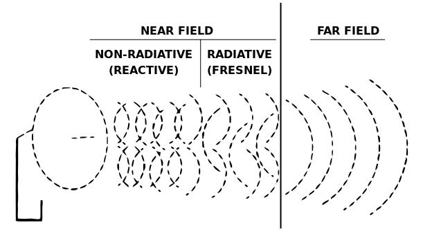
Here's a picture that might help: - enter image description here

The picture shows a dish antenna but quite simply it is an antenna just like a piece of wire or a trace on a PCB BUT remember, the dish is designed to emit efficiently at a particular frequency whereas tracks and wires may "resonate" at several wavelengths.

Close to the wire/dish/trace/antenna, electric fields and magnetic fields are produced that store energy just like inductors and capacitors do - these fields (close to the antenna) do not radiate very far. Notice in the picture, the dotted lines overlap and intersect each other - the picture is trying to represent an "incompatibility" between E and M fields. I'm looking for the correct word to use here... I thought "incoherency" but maybe not, maybe there is a better word rather than incompatibility.

As distance increases towards the equivalent of about 1 x wavelength, if the antenna is efficient, the E and M parts start to "align" in time i.e. their amplitudes rise and fall together. Before that (in the near field) there is a cacophony of misalignment which is mainly due to the L and C of the antenna - the E and M fields are not aligned in time and in fact, the E and M fields around the antenna can be misaligned seemingly almost haphazardly.

As distance increases AND if the antenna is good at doing its job, in what is known as the far-field, proper EM waves are produced. It's still a very mysterious phenomena to me!

\$\endgroup\$
2
\$\begingroup\$

As you know, a steady current through a wire is surrounded by a magnetic field, the strength of which is proportional to the current. You're probably also familiar with the mechanism of induction; a changing magnetic field creates an electric field. By extension, a changing current gives rise to an electric field outside of the wire, a property often used to transfer energy between two conducting coils. The magnitude of this electric field is determined by the rate of change of the current and thus the frequency.

Not only does a changing magnetic field spawn an electric field, it also works the other way around. In an electromagnet, an alternating electric field is used to produce a magnetic field. Around the wire, in what is approximately 'free space' (no currents or charges), the two fields are creating new generations around one another all the time, although these are in reality not as discrete as this explanation suggests. New generations contionusly push the wavefront forward. This is the electromagnetic wave.

Despite the apparent simplicity of the equations involved, calculating the propagation of electromagnetic fields is fairly advanced even for the simplest idealised geometries, but it's easy to induce from knowledge of the mechanism (and mathematically from the time derivative in Maxwell's equations) that the intensity of the EM waves around a wire is related to the frequency of its current, for the change in current caused the wave. Conductors carrying low-frequency currents radiate as well, but only slightly.

\$\endgroup\$
1
  • \$\begingroup\$ In my University course they did show us the Maxwell equations but never made us do the hardwork with them. It was like this is the equation and here is an example to use it. They never went into how it is derived and why EM waves start getting emitted at higher frequecies and they always stressed how hard it is to use them for an nontrivial case. \$\endgroup\$
    – quantum231
    Commented Apr 27, 2013 at 20:02

Your Answer

By clicking “Post Your Answer”, you agree to our terms of service and acknowledge you have read our privacy policy.

Not the answer you're looking for? Browse other questions tagged or ask your own question.