1
\$\begingroup\$

I am pretty sure this is a very easy question but I am having brain lag, on a digital/analog voltmeter, what is the difference between zero volts (or very close to zero i.e. 10 mV, -4 mV ) when the meter probes is left open circuit, floating, and zero volts when really the electric potential difference between the two probes is zero volts.

The reason for this existential question, is debugging something in an automobile, I was thinking how to know whether the voltmeter probes really had correct contact and read 0 volts, or I did not have a correct contact and the voltage I am reading on the probes is just the meter floating (on a digital multimeter)

Maybe really the potential difference between the probes is zero volts? i.e. If I carry a beefy big electron from one probe to the other, I need almost no energy? If this is even true how to differentiate between this and that really the two points in the circuit I am measuring is really zero volts.

\$\endgroup\$
2
  • \$\begingroup\$ Floating leads producing non-zero display might be suspicious, but here's another test you can do: measure your voltage both ways by switching probe position. One reading will be positive, while the other is negative...ignoring the sign, are the magnitudes the same? A 0V check is best done by shorting probes together (without shorting the device you're testing!) \$\endgroup\$
    – glen_geek
    Commented Jul 2, 2023 at 15:41
  • \$\begingroup\$ Would a beefy big electron be a tau particle, I suppose? \$\endgroup\$
    – Hearth
    Commented Jul 2, 2023 at 16:33

4 Answers 4

2
\$\begingroup\$

If I carry a beefy big electron from one probe to the other, I need almost no energy?

That's about it (apart from electrons being all the same size). Whether you need (essentially) no energy because the probes are unrelated and the electron has no route to get back, or because the route back is available but without a difference in potential is something that a voltmeter will not tell you.

If you want to know the difference, put an 1.5V battery in series with the voltmeter such that all readings are 1.5V too large. Then 1.5V will get displayed for a short, and 0V will get displayed for on open connection (assuming that the input resistance of the voltmeter is not more than a few Gohm and will not react to static electricity).

\$\endgroup\$
1
\$\begingroup\$

Just a few thoughts here in no particular order of importance ...

  1. Having had enough trouble over the years, I always give my DMM probes the "wiggle test" Connect either to a known impedance ( say, 1K ) or a voltage source ( say, 1.5V or 12V ). With probes firmly contacting the impedance or voltage. Then, wiggle the probe cables, noting if the DMM's reading shows any significant change. This ought to verify the integrity of the DMM and its probes.
  2. As for beginning to check the car, make sure there is very nearly zero ohms of impedance between the battery's ground terminal and a metallic point on the car's chassis. A reading of zero ohms assures the interity of the batteries ground terminal to the cars chassis.
  3. Make sure the car's battery is between about 11VDC and 16VDC ( engine off ). - Batteries are not precision voltage sources, btw.

Good luck.

\$\endgroup\$
1
\$\begingroup\$

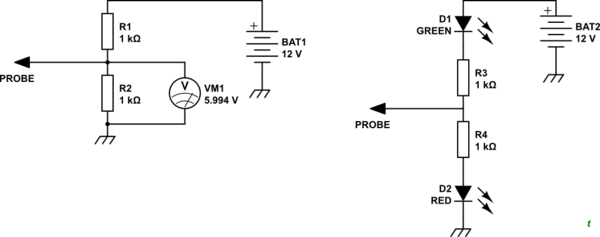
A digital meter will have a weak pull-down of 1 MΩ to 10 MΩ that causes it to read 0 V when floating.

You can clear the ambiguity in many cases by biasing the multimeter to about 6 V or so with a pair of resistors.

schematic

simulate this circuit – Schematic created using CircuitLab

For automotive work you generally just want to know whether you've got contact or not. The LED circuit above will light both red and green LEDs weakly when the probe is floating. When the probe is connected to +12 V the green light will be shorted out and the red will light brightly. Similarly touching chassis will short out the red LED and the green will light brightly.

\$\endgroup\$
1
\$\begingroup\$

The DMM shows the voltage no matter what is connected to the input. There is usually a 10 MΩ input shunt resistance across the inputs and that’s the only way it can show zero when the leads are open. Otherwise it’d drift all over the place. That’s all really.

\$\endgroup\$

Your Answer

By clicking “Post Your Answer”, you agree to our terms of service and acknowledge you have read our privacy policy.

Not the answer you're looking for? Browse other questions tagged or ask your own question.