2
\$\begingroup\$

I need to build a circuit that takes a 12v DC input and produces a 5v DC 30Hz square wave.

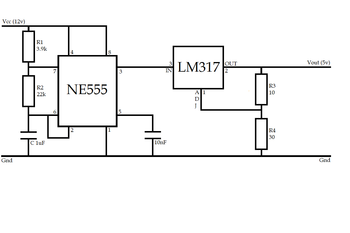
My thinking is to produce the square wave using a 555 in an astable oscillator configuration, and then step the voltage down to a reasonably accurate 5 volts using an LM317. I have used online calculators to arrive at the resistor and capacitor values for both halves of the circuit, but am not sure if I can just combine them as I have here in the picture.

  1. Will the circuit I have drawn operate as I am expecting?
  2. Is there a better way of doing this?

For what it is worth, I am trying to help somebody bypass VATS/PassKey on an old Corvette, and the ECU/ECM expects the 30Hz signal on one of its pins to turn the injectors on. The circuit will only be powered while the ignition is cranking, so heat/power dissipation should be relatively brief.

Thank you.

enter image description here

\$\endgroup\$
4
  • \$\begingroup\$ Where did the 30 Hz signal come from before? Do you know anything about the component or circuit that produced it? \$\endgroup\$
    – AnalogKid
    Commented Jul 26, 2023 at 12:27
  • 1
    \$\begingroup\$ LM317 is a voltage regulator, intended to be used for DC power supplies. I wouldn't expect your circuit here to work very well at all. Either regulate the DC supply voltage to your 555 so that it produces the output you want, or use a voltage divider or zener on the output (followed by a buffer if required). \$\endgroup\$
    – brhans
    Commented Jul 26, 2023 at 13:56
  • \$\begingroup\$ WE wouldn't call this a "12V input" -- we'd call it a 12V power supply. \$\endgroup\$ Commented Jul 27, 2023 at 15:20
  • \$\begingroup\$ @AnalogKid There's a black box on the wiring loom that manages security. I haven't seen the inside of one, but I gather it's potted or a custom IC or something, because they're regarded as unserviceable. \$\endgroup\$
    – Andrew C
    Commented Jul 29, 2023 at 6:44

7 Answers 7

7
\$\begingroup\$

Build the circuit the other way around i.e. First 12V to 5V with 317, then drive the oscillator with 5V.

Alternatively, you can drive 555 with 12V directly and use a divider (or a resistor+Zener) at the output to get 5V, then buffer if necessary (e.g. when the target system is not happy with output impedances of a few hundreds of Ohms).

\$\endgroup\$
1
  • \$\begingroup\$ Thank you for the suggestion. \$\endgroup\$
    – Andrew C
    Commented Jul 29, 2023 at 6:45
3
\$\begingroup\$

The LM317 normally requires a capacitor between the input and ground. If you put one in, it will affect your square waves. If you omit it, the LM317 might be unstable. Or not. Sometimes things work even when they have design issues.

\$\endgroup\$
3
\$\begingroup\$

You can, but you shouldn't do this – the LM317 (at least those I worked with) really isn't very stable without an input capacitor (between LM317's IN and Gnd). But with that capacitor, you'd heavily load the NE555, and not get a good square wave. (see Math keeps me Busy's answer)

Rohat is also right – your LM317 doesn't "pull low", it just tries to "pull up", so the "off" state of your 5V will be bad.

All in all, this really isn't the chips you should use for this simple task.

Much more sensibly, use a 5V supply (which you could easily get, e.g. using an LM7805, or if you need to supply more than 0.3 A, a SMPS step-down "buck" converter module). Depending on the frequency accuracy you need, a very simple 3-inverter ring oscillator (with RC "delays" in between) might do, or you use a CMOS 555 (e.g. LMC555) variant (or really, a microcontroller) to produce the 5V – the NE555 is a really bad choice here, because of its unreasonably high supply voltage requirements and high voltage headroom.

If the output of whatever you use (microcontroller, ring oscillator, or LMC555) isn't strong enough to drive your load, you can add two transistors (typically, a logic level N-channel MOSFET and a logic level P-channel MOSFET) as push-pull output stage.

\$\endgroup\$
1
  • \$\begingroup\$ Thank you for that. \$\endgroup\$
    – Andrew C
    Commented Jul 29, 2023 at 6:45
2
\$\begingroup\$

Most voltage regulators expect to work at DC. You can run a CMOS 555 from 5V and it will do what you want, no fuss. Then you can use a linear regulator to get 5V out from 12V. That would be I think the simplest circuit.

You could also:

  1. Use a precision clamp, and run the 555 and the op amp from 12V.
  2. Use the 555 to drive a CMOS switch like 4066, flipping the output between a 5V reference voltage and 0V.

The 5V reference can come from one of the ubiquitous adjustable references like say TL431. Just bypass it properly so the reference doesn’t mind the switched load.

Although if you’re using a 4066 you may as well throw in a 4521 with a crystal or ceramic resonator attached, followed by a 4059 to divide it down to 30Hz.

A 555 won’t have a good tempco unless you optimize it carefully - but if a 555 has enough accuracy for your need, then it’s of course fine to use it.

\$\endgroup\$
1
  • \$\begingroup\$ Thank you for that. \$\endgroup\$
    – Andrew C
    Commented Jul 29, 2023 at 6:46
1
\$\begingroup\$

If you decide to put the regulator in front of the 555, set the 317 output to 6 V. This will compensate for the 555 headroom requirement. That is, the output stage is not "rail-to-rail" - its peak output voltage is at least 1 V less that its supply voltage. This is detailed in the datasheet. The ECU probably does not require an exact 5 V amplitude pulse, but it might not be happy with something down around 3.5 V.

\$\endgroup\$
1
  • \$\begingroup\$ Cool. Thanks for that tip. \$\endgroup\$
    – Andrew C
    Commented Jul 29, 2023 at 6:48
0
\$\begingroup\$

It is not necessary to generate a 12v 30Hz signal and convert the 12volt peaks to 5volts. That's the hard way. The easy way is to regulate 12Volt DC to 5V DC, and then generate a 30hz signal from the 5volt supply.

It would be easier to use a dedicated 5 volt regulator such as the LM7805 instead of the LM317.

Using the LM317 requires more parts to set the output voltage, whereas the LM7805 has a preset output voltage and only requires input and output filter capacitors to filter an AC ripple or the noisy 12v automotive supply and then buffer the output supply for a varying load. The LM317 output voltage is set with an R1 and R2 resistor, one of them should be a multi-turn trimmer resistor.

Either regulator will produce heat during its operation, varying based on the load and difference between the input supply voltage and the regulated output voltage. Attach the metal tab on a TO-220 type case device to something metal to dissipate the heat. The metal tab is internally connected to the {ground|earth|neutral|common ground} supply. Miniature versions of the LM705 devices can look like a small transistor and have no heat sink tab, and supply a tiny circuit like yours.

https://www.sparkfun.com/datasheets/Components/LM7805.pdf

You can then use an 7400LS series quad NAND gate (74LS00) or a CMOS quad NAND gate (74HC00) to make a clock circuit, with an RC (resistor capacitor) tank circuit to tune it to 30Hz. Keep the signal isolated from other signals like the spark plug wires, obviously.

see NAND gate RC controlled clock circuits here https://www.homemade-circuits.com/simple-circuits-using-ic-7400-nand-gates/

Specifically this one https://www.homemade-circuits.com/wp-content/uploads/2019/10/LOW-FREQUENCY-AUDIO-OSCILLATOR-circuit.png

The NAND device has 4 devices in one DIP case. You can buffer (strengthen the output signal by using the two remaining NAND devices in parallel.

Never leave TTL device inputs unconnected on your circuits, they can use power if they are in an electrically noisy environment, and receive Ghost inputs, and then amplify the signal when the resulting output signal changes. Typically, boards with unused inputs are tied to a rail (+5v power, ground, Vcc Vdd Vcc etc) or pull up resistor to Vcc (+5v). Some designers intentionally use exposed cuttable traces for this so they can be cut and reporpoised for emergency uses such as inverting a signal. Never connect 74LS00 inputs or outputs to the distributor- Just sayin'.

\$\endgroup\$
2
  • \$\begingroup\$ As far as anyone driving a TTL signal through a CMOS Quad Bilateral Switch (4066) I would think the 50ohm impedance through it might become problematic or unreliable. Those are better used to play with audio signal injection in some whacky guitar effects pedals than in controlling TTL signals. \$\endgroup\$ Commented Jul 27, 2023 at 15:03
  • \$\begingroup\$ Thank you for the detailed reply. \$\endgroup\$
    – Andrew C
    Commented Jul 29, 2023 at 6:47
0
\$\begingroup\$

Use a spare, outdated Arduino. Lots of people have old Arduinos lying around.

\$\endgroup\$

Not the answer you're looking for? Browse other questions tagged or ask your own question.