How to reveal the inverting idea
A good approach to understanding the inverting amplifier is to start by examining, step by step, the simpler non-inverting amplifier. This allows one to see the rationale behind this more complex circuit solution.
Since the question is conceptual, we will use conceptual circuits where the role of transistors is performed by man-controlled voltage sources and resistors.
Negative feedback
Paradoxically, we aim to create a unity-gain amplifier using an amplifier with a gain that is thousands and even millions of times greater; but the purpose of this is to achieve precision and stability. We do this through the principle of negative feedback: the output voltage is compared to the input voltage and adjusted accordingly, so that the difference between them becomes zero.
Non-inverting follower
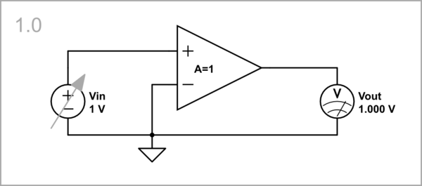
simulate this circuit – Schematic created using CircuitLab
Man-controlled output voltage source
According to the general idea above, the simplest negative feedback circuit can be made by a subtractor and a non-inverting amplifier (op-amp). The loop can serve as a subtractor if we connect the two voltages in series. We can serve as an “amplifier” if we control the output voltage so that the null indicator NI shows zero voltage difference Vin - Vout = 0.
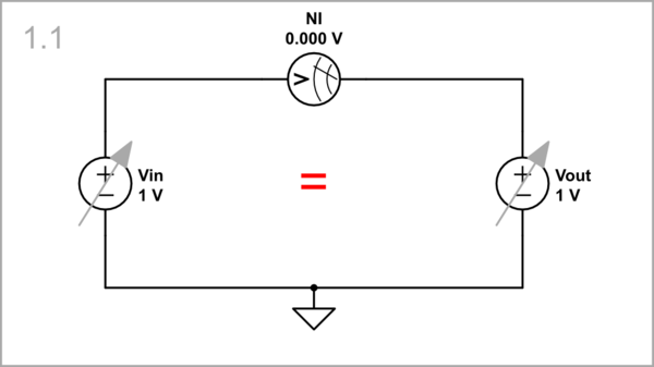
simulate this circuit
Behavioral voltage source
We can automate this procedure by replacing Vout with a behavioral voltage source that copies the input voltage.
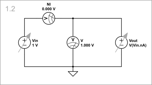
simulate this circuit
Op-amp follower
In the practical circuit of an op-amp follower, an op-amp serves as the output voltage source Vout. Note that it must have a "floating" (differential) input. In some cases, it can be single supplied (with only a positive voltage source of +10 V).
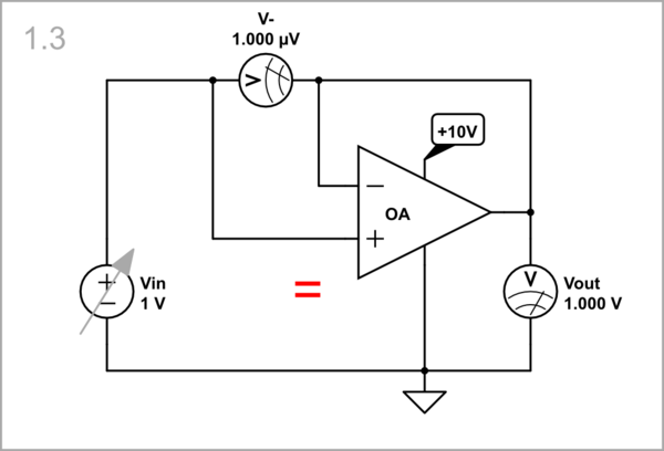
simulate this circuit
Inverting follower
simulate this circuit
Man-controlled positive voltage source
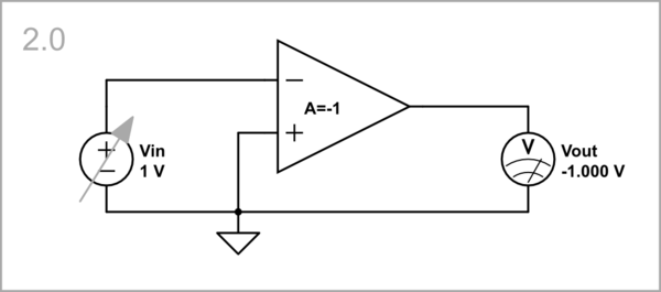
In other cases, we need an “inverting follower”. It can be implemented by a summer and an inverting amplifier (op-amp). The summer is implemented by two resistors in series (aka "voltage divider"). As above, we can serve as an “amplifier” if we control the output voltage so that the null indicator NI shows zero voltage difference.
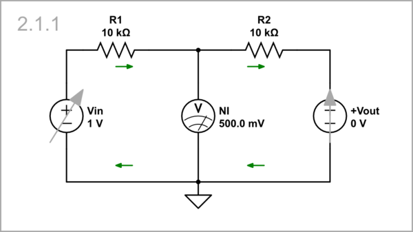
simulate this circuit
However, a problem arises here. For the R1-R2 resistor network to function as a subtractor, the output voltage Vout must go below zero (the Vout source must be negative).
Single-supplied op-amp follower
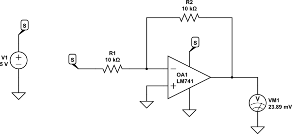
So, this is the problem of the single-supplied op-amp inverting amplifier:
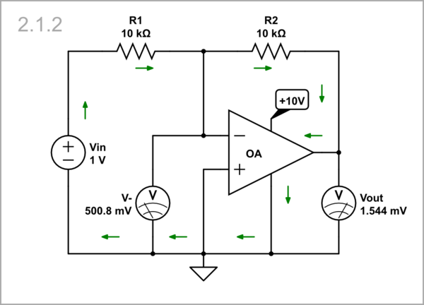
simulate this circuit
... the output voltage of an op-amp powered by a positive voltage cannot become negative.
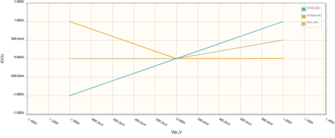
Man-controlled voltage source
So, in the conceptual circuit, the output voltage source Vout must be negative.
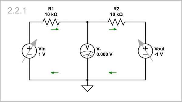
simulate this circuit
Behavioral voltage source
The same is true for the automated circuit with a behavioral voltage source.
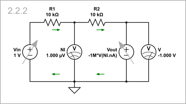
simulate this circuit
Then the result is perfect.
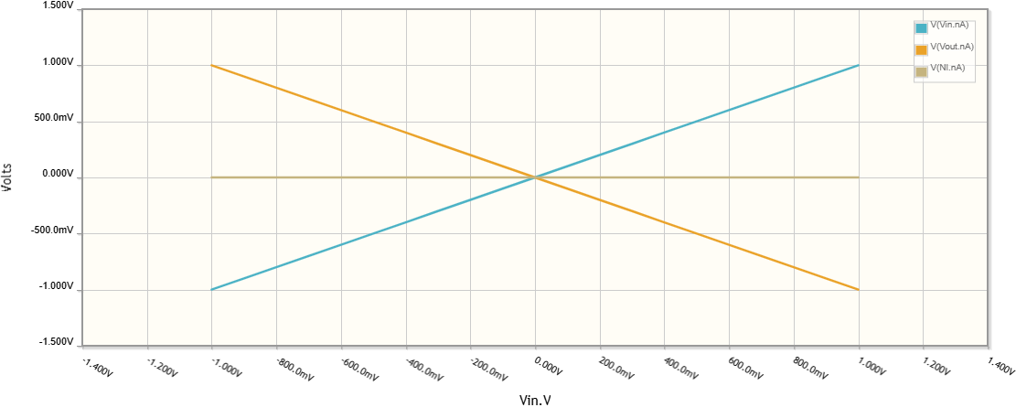
Op-amp inverting follower
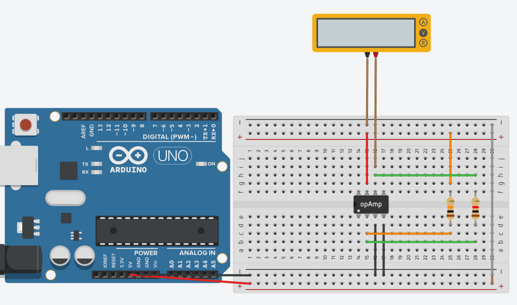
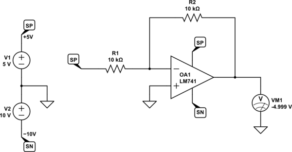
This means that in the practical circuit of an inverting amplifier, the op-amp must be supplied by a bipolar voltage source (split supply)...
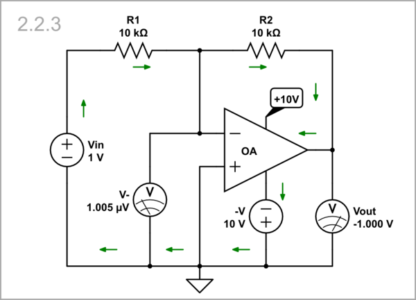
simulate this circuit
... and the result is perfect.
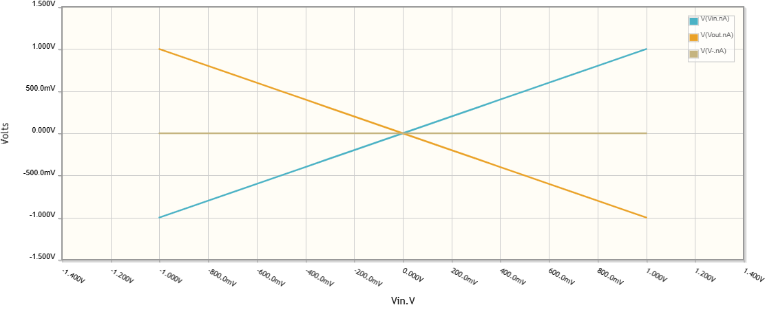
What is inside the op-amp output?
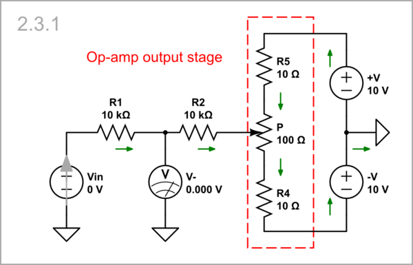
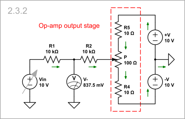
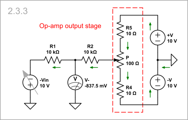
The root of confusion when dealing with op-amp circuits often lies in a limited understanding of the op-amp's internal workings. To grasp a specific circuit, it is crucial to visualize the output stage. A simplified model of this stage resembles a voltage divider, with additional low-value resistors (or diodes) connected to its terminals.
Vin = 0 V: When operating in a region where the output voltage is distant from the supply rails, the op-amp is capable of compensating for the input voltage.
simulate this circuit
Vin = 10 V: However, if the output voltage reaches either the negative...
simulate this circuit
Vin = -10 V: ... or positive supply rail...
simulate this circuit
... it stops changing and ultimately fails to compensate for the input voltage.
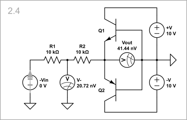
Real output stage
Inside the op-amp, the "potentiometer" is implemented using two complementary transistors.
simulate this circuit

