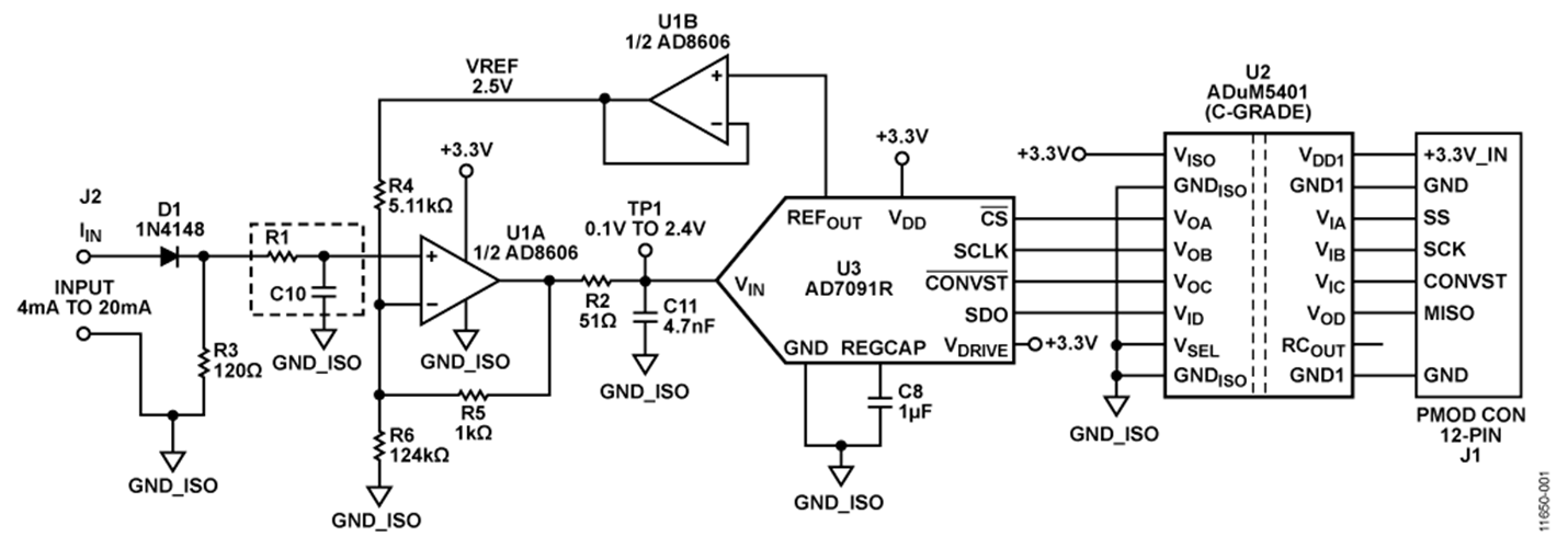
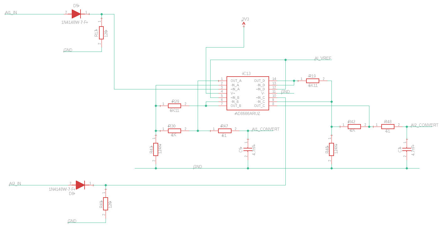
It sounds like the main current draw is the op-amp. AD8608 advertises ~1mA/amp or 4mA total here. With a 10MHz GBW product, this will give rapid settling for the 300kS/s advertised in the original circuit, but with a sample rate at most a few per second, this is entirely wasted power for you. It's a poor choice.
There are precision micropower op-amps available; MCP6V19-E/ST seems quite viable here.
A faster amp can also be switched on for a reading; you would need an additional digital input to convey this (or at least a pulse detector on SPI, and you discard the first sample then quickly resample, and then it turns itself off after a time delay). Suitable types need to not load the input, else parasite power is drawn through the REF pin if nothing else; or VREF could be switched with an analog switch (e.g. 74HC1G66). Supply could then be switched with a PMOS (BSS84?) or other load switch.
Incidentally, I'm not seeing many op-amps rated for non-loading inputs like this; ironically MCP6V19 is one of the exceptions, but its consumption is low enough to perhaps not need it, already. (Pay attention to the input ESD, protection and limiting section in the datasheet. My interpretation is, it can be overvolted gently, powered up or not, so will tolerate a supply switching scheme; but it may be there are other limitations they don't document which show up in such an operating mode. Or if it might be more vulnerable in such a state.)
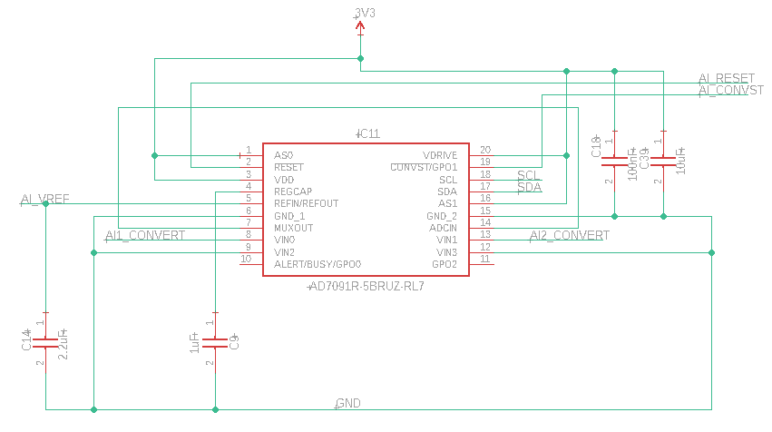
In any case, that seems a possibility to reap more savings in your application, should you need it. Next, the ADC would be pulled into question, and I would suggest a sigma-delta type which is available in low sample rates, potentially higher bit depth if that should be desirable, and lower clock rates and current consumption, while being relatively immune to input noise between sample and clock rates (due to its integrating design) so that input filtering requirements can be relaxed a bit.
Pay attention to filtering the inputs; with an analog bandwidth of some 10s kHz for this op-amp type, expect errors to show up for any signals outside that bandwidth: asymmetrical slewing and input rectification can turn higher frequencies into DC offsets, and madness ensues. An RC filter of some Hz cutoff frequency would seem more than sufficient here. (You probably want to avoid type 2 dielectric ceramics, as they are nonlinear, hysteretic and microphonic. Electrolytic aren't very stable (esp. varies with temperature), and may prove leaky. Film would be ideal, but you may also find this is a suitable application for tantalum.)
Without adding more op-amps (and of adequate GBW to handle the less-filtered or unfiltered inputs), I suppose active filters are out of the question, so a 1st or 2nd order RC filter with a cutoff somewhat above what you need, will have to do. This forces settling time to be rather slow, as you can't speed up the transfer function with the presence of complex poles.
Speaking of input rectification, note that the diode shown, while it does ensure specified current flow direction, it is also susceptible to RF interference. As long as the developed DC offset is absorbed by the current loop, this can be fine (within compliance range; which is most likely more than enough until ludicrous RF input, but, maybe it's not, you'd have to check), but there will be transient error as the interference keys on/off; this would be more of a problem for the original (higher bandwidth) circuit than here, but more to the point, we can avoid this concern entirely by merely filtering the input at the connector. A ferrite bead and couple nF capacitor will most likely suffice.


