0
\$\begingroup\$

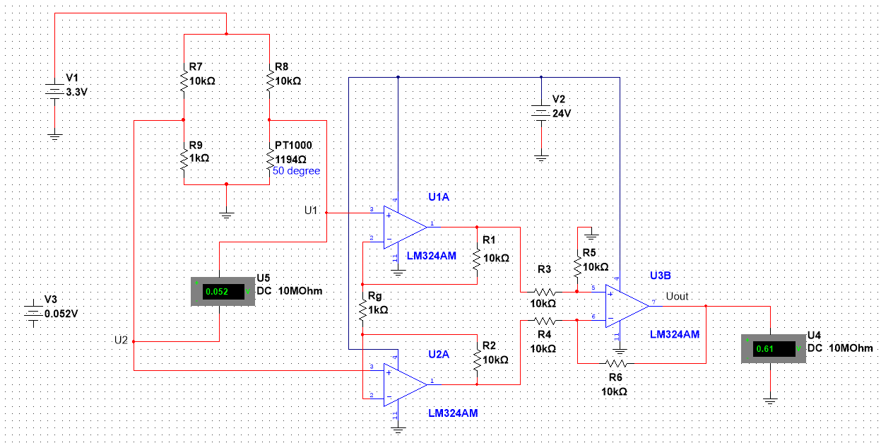
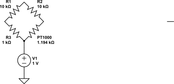
I have set up this circuit: Instrumental amplifier with Wheatstone Bridge

I measure an output of 0.61 V from the instrumentation amplifier. The gain of the amplifier is set to 21. The formula for the output is given by: Uout=(1+2R1/Rg)×(R3/R2)×(U1−U2) Given an input of 0.052V, I would expect the output to be: 0.052×21=1.092V... Why am I observing a different value?

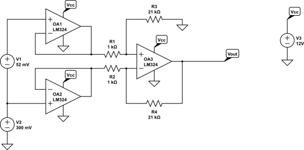
When I set it up with an external voltage difference, which is also 0.052V: Without Wheatstone Bridge
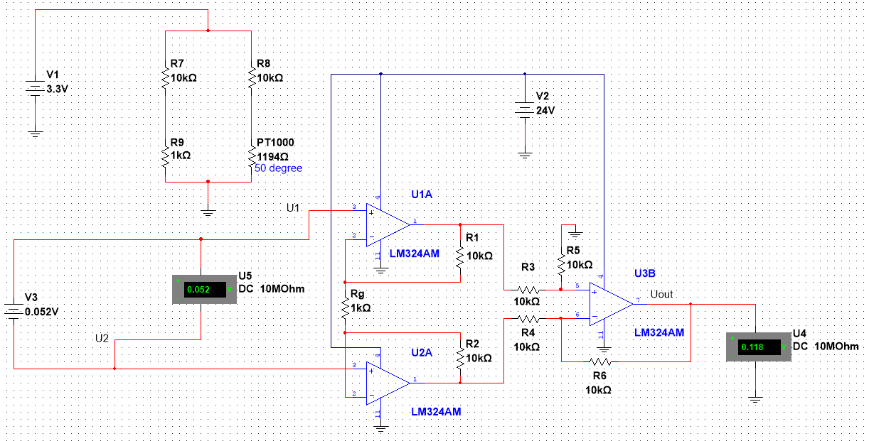
I get the expected output signal. So, why is there a discrepancy when using the Wheatstone bridge? Is there something I can adjust to get accurate readings with the Wheatstone bridge? Or is there another method commonly used to measure temperature accurately?

I'd like to note that the behavior on the breadboard matches what I observed in the simulation, and I have tried with different op amps.

Update:

Thank you for the replies everyone,

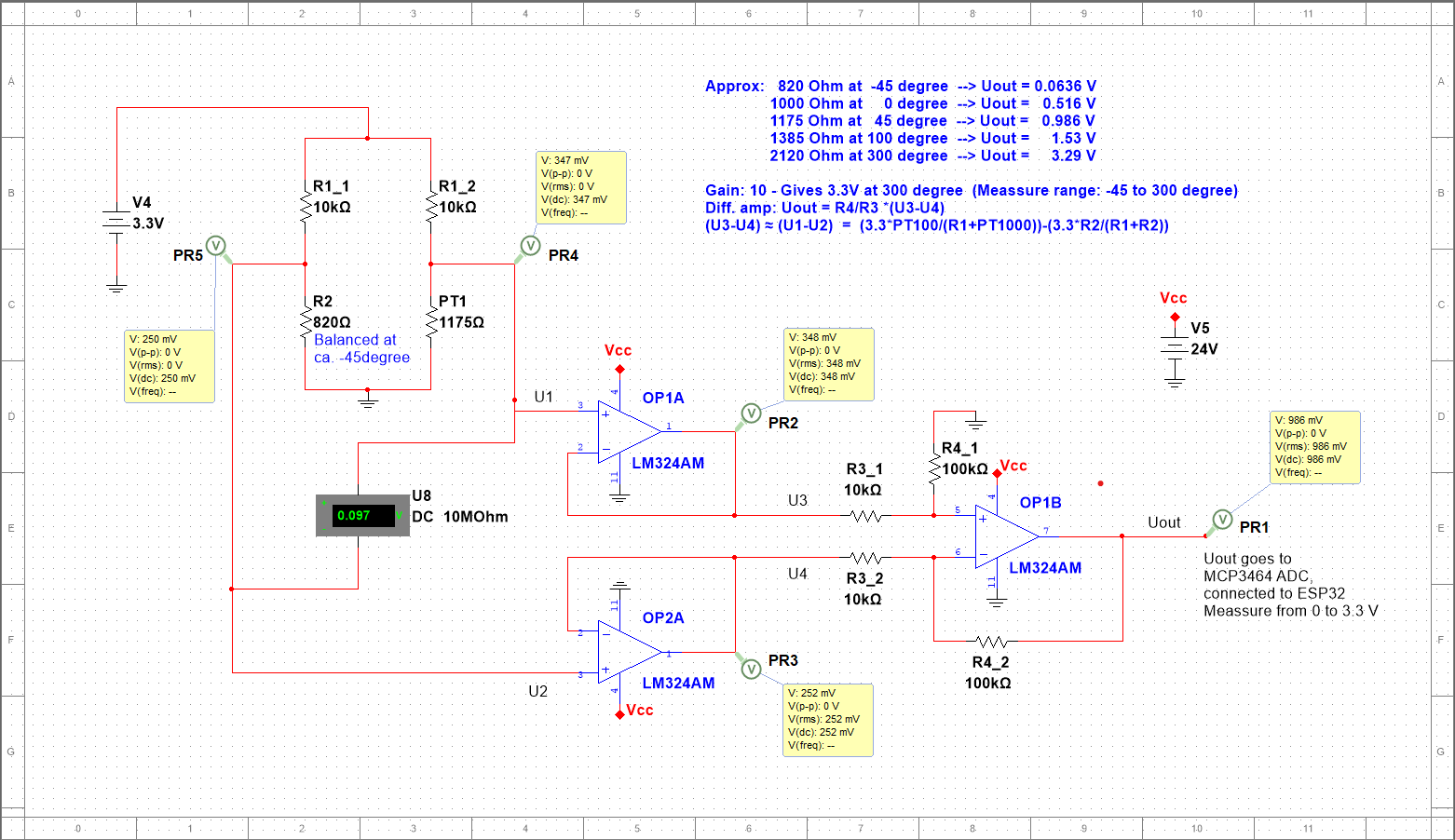
I've tested the alternative circuit quite a bit and so far, it seems to work really well. (Both on breadboard and simulation)

Regarding the low current at the output, would this be an issue when the output is only going to an ADC (MCP3464)? There shouldn't be any current going into it, right?

I'll be measuring temperatures typically ranging from -20 to 200 degrees and have set the extremes to -45 to 300. (so that the bridge is balanced at -45). Using OP1A and OP2A as buffers, will this cause any problems? Isn't it better to have them here as a "current stopper"? I have also adjusted the gain to 10 to match the ADC, and increased the resistors in the differential amplifier as stated :)

enter image description here

I'm relatively new to electrical circuits, so I really appreciate all the help :)

\$\endgroup\$
2
  • \$\begingroup\$ Shouldn't your second term be R6/R4? Your output stage has a gain of 1 \$\endgroup\$ Commented Aug 8, 2023 at 12:27
  • 1
    \$\begingroup\$ Sorry, the formula was for another circuit so her it should have been Uout=(1+2R1/Rg)×(R6/R4)×(U1−U2) since R1=R2, R3=R4 and R5=R6 as you stated :) \$\endgroup\$
    – Eirik
    Commented Aug 8, 2023 at 12:36

4 Answers 4

3
\$\begingroup\$

In the top circuit, U2A is saturating at the negative rail. If you add a negative 12V supply rather than using ground it should give close to the expected values.

The second circuit also won't work in practice because you have no path for the op-amp bias currents (V3 is floating) but whatever parasitic resistances your simulator has allowed are permitting it to give a sensible but incorrect answer.

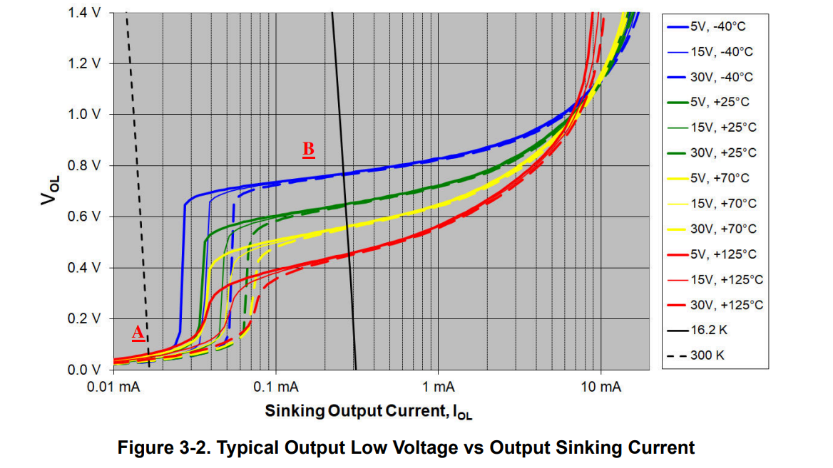
@MathKeepsMeBusy +1 has an alternative circuit that does not require a negative supply, however the resistors should be increased in value by perhaps 10:1 (even though that causes some increase in other errors) or else you may run into another gotcha (the first being the limits of the classic instrumentation amplifier approach):

Here is the typical performance (individual units may vary, so you can't depend on it being this good or bad):

https://whatgear.com/pro/flume/sugar-bytes-turnado-action-multi-fx-vst

If you need the output to be at 300mV you can't count on more than 15 or 20uA worst-case.

In reality you'd probably give this a bit of thought and use fewer amplifiers. U2A is doing little to nothing of value and is causing issues.

\$\endgroup\$
3
\$\begingroup\$

Spehro Pefhany's answer is correct.

The voltage above R9 is 1/11 * 3.3 = 0.3 V. The voltage above the PT1000 is 0.352 V. The common mode voltage is thus (0.3 + 0.352)/2 = 0.326 V.

The front end of the instrumentation amplifier "expands" the differential voltage while keeping the common mode voltage the same. (At least that is what it does when not in saturation).

The expanded differential voltage should/would be 1.092 V. The lower input voltage should/would be 0.326-(1.092/2) = -0.220 V, which is below the negative rail of the LM324, resulting in op-amp saturation.

An alternative to using a dual rail power supply for the op-amps / instrumentation amp, is to move some or all of the amplification from the instrumentation amp's front end, to the IA's difference amp "back end".

schematic

simulate this circuit – Schematic created using CircuitLab


Edit: Another solution would be to add a voltage source, or even a resistor between the negative side of the Wheatstone bridge and ground (provided the PT1000 is not grounded itself.)

schematic

simulate this circuit

The voltage of the inserted voltage source is not critical, but needs to be enough to correct the saturation problem.

\$\endgroup\$
1
\$\begingroup\$

An alternate solution to this problem, which may or may not be amenable, is to provide a reference offset to the side of R5 that's currently grounded. You need a low-impedance source, like a precision reference, to do this.

Say you split the rails with a 12V reference. Then, a zero-differential input will yield a 12V output. The gain remains the same.

This will work as long as you can tolerate the output offset, and as long as the inputs remain in the allowed input range for the opamps (which shouldn't be a problem for a Wheatstone Bridge).

The approach may be more feasible than adding a negative rail to your design.

\$\endgroup\$
1
\$\begingroup\$

When using basic general-purpose op-amps, such instrumentation amplifier circuits underperform when compared to other approaches.

Given the supply voltages available, the simplest and most accurate approach with LM324s is:

  1. Non-inverting buffer for the left output from the bridge.

  2. Driver for the excitation voltage that keeps left bridge output at a fixed common-mode voltage.

  3. A single-ended non-inverting amplifier for the other bridge output, referenced to the same common mode voltage.

  4. (Optional) a follower for the output voltage, or split the gain across two stages for better DC performance.

The whole thing fits on a quad op-amp like LM2902.

Since one bridge output has a fixed voltage, there’s no need for differential amplification.

It can be then powered from 5V; 24V is overkill. And it will also work from any modern low voltage rail-to-rail op amp.

If you’d want to go super-retro while keeping supply voltage at 3.3V then a single LM10 could do the job with some creativity. The reference voltage amp could be used to control the excitation voltage, and the op-amp would deal with single-ended amplification. A four-op-amp solution is better. No precision resistors are needed for as good a CMRR as the op-amps will allow.

\$\endgroup\$

Your Answer

By clicking “Post Your Answer”, you agree to our terms of service and acknowledge you have read our privacy policy.

Not the answer you're looking for? Browse other questions tagged or ask your own question.