2
\$\begingroup\$

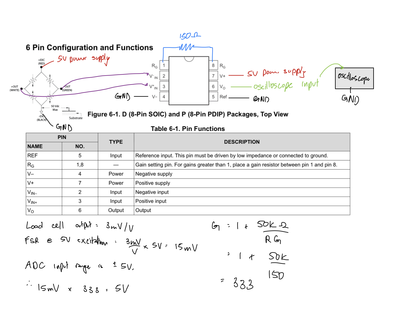
Is there any issue with the wiring or calculations of my INA128 instrumentation amplifier to my load cell Wheatstone bridge? Currently I see no change in the output when connected to the oscilloscope. I know the load cell works because I see a change without the amp at a very high gain on the scope.

Here’s the calculations and how I have it wired:

enter image description here

Here’s a link to the datasheet of the amp: enter link description here

\$\endgroup\$
3
  • \$\begingroup\$ Per datasheet, Page 15: "The most common application is where the output is referenced to ground when no input signal is present by connecting the REF pin to ground, as Figure 9-1 shows. In single-supply operation, offsetting the output signal to a precise midsupply level is useful (for example, 2.5 V in a 5-V supply environment). To accomplish this level shift, a voltage source must be connected to the REF pin to level shift the output so that the device can drive a single-supply ADC." \$\endgroup\$ Commented Jun 25 at 13:30
  • \$\begingroup\$ Also, make note of the compressed Vout range if you're operating with a single +5V supply. As well as Figure 7-6. \$\endgroup\$ Commented Jun 25 at 13:32
  • \$\begingroup\$ Is the output stuck near zero? If so, have you tried swapping the inputs? \$\endgroup\$ Commented Jun 25 at 14:59

2 Answers 2

2
\$\begingroup\$

If you want an INA128 to output between 0V and 5V, you'll have to supply it with something like -3V and 8V (off the top of my head), with gain >5. Look in the datasheet at the input vs. output range vs. gain - so-called Diamond Plot.

Currently I see no change in the output when connected to the oscilloscope.

That's because the correct (expected) output voltage is out of the allowed output voltage range when operating from 0V,5V supplies.

An INA128 will also do very poorly at driving an ADC. It will drive slow ADCs OK, but anything with a capacitive sampling input will corrupt the output of the in-amp and cause all sort of problems - most of them look like DC linearity errors and will often go unnoticed until the product is out of the door. I've seen people get caught by that.

You have some options:

  1. Use a wider supply range for INA128, and add an op-amp buffer to drive the ADC.

  2. Use a rail-to-rail output in-amp, and optionally add an op-amp buffer to drive the ADC.

  3. Use a modern ADC (like you really should) that can connect directly to the strain gage without any preamplification. Most 24-bit ADCs will do that job just fine.

\$\endgroup\$
1
\$\begingroup\$

Your connections and choice to tie Vref to ground seem fine to me.

You don't, however, describe what you are seeing at the output beyond a vague "no change".

I suggest that if the output is saturated at one of the rails, though, that the problem may lie in the bridge itself, as you don't show any clear mechanism to balance the bridge. Often, you'll see a potentiometer that can be used to trim out the bridge so that you can trim out any offset. With a gain of 333, it doesn't take must of a mismatch (just a few tens of millivolts) to saturate your circuit.

You're first debugging step should be to test your circuit with a function generator instead of a bridge to rule out this issue.

\$\endgroup\$

Your Answer

By clicking “Post Your Answer”, you agree to our terms of service and acknowledge you have read our privacy policy.

Not the answer you're looking for? Browse other questions tagged or ask your own question.