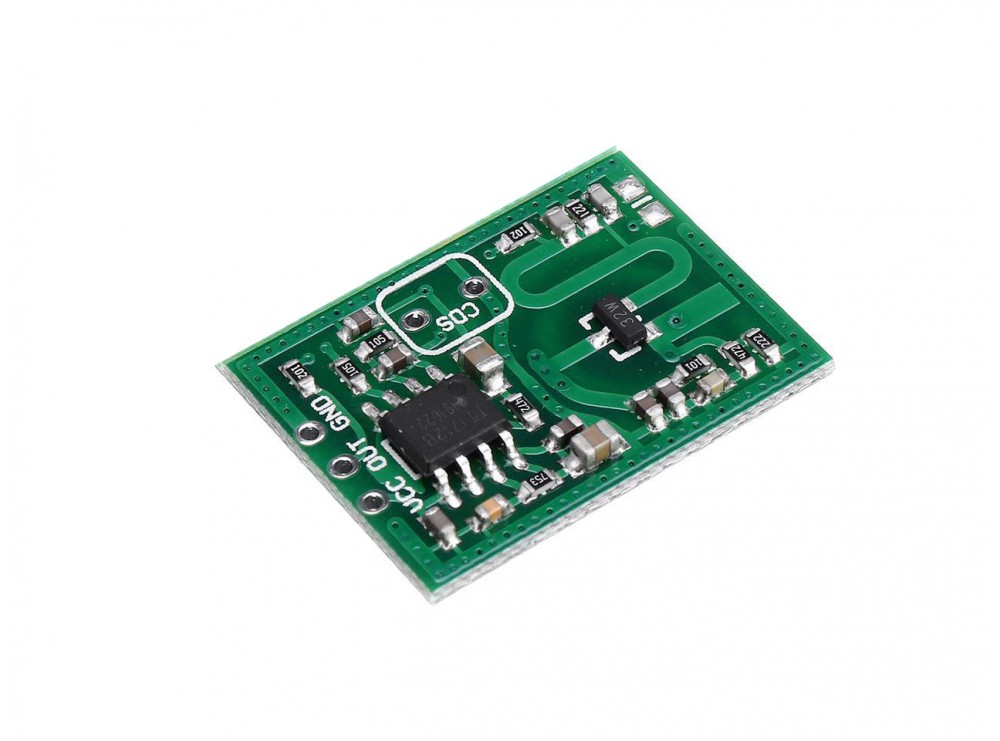
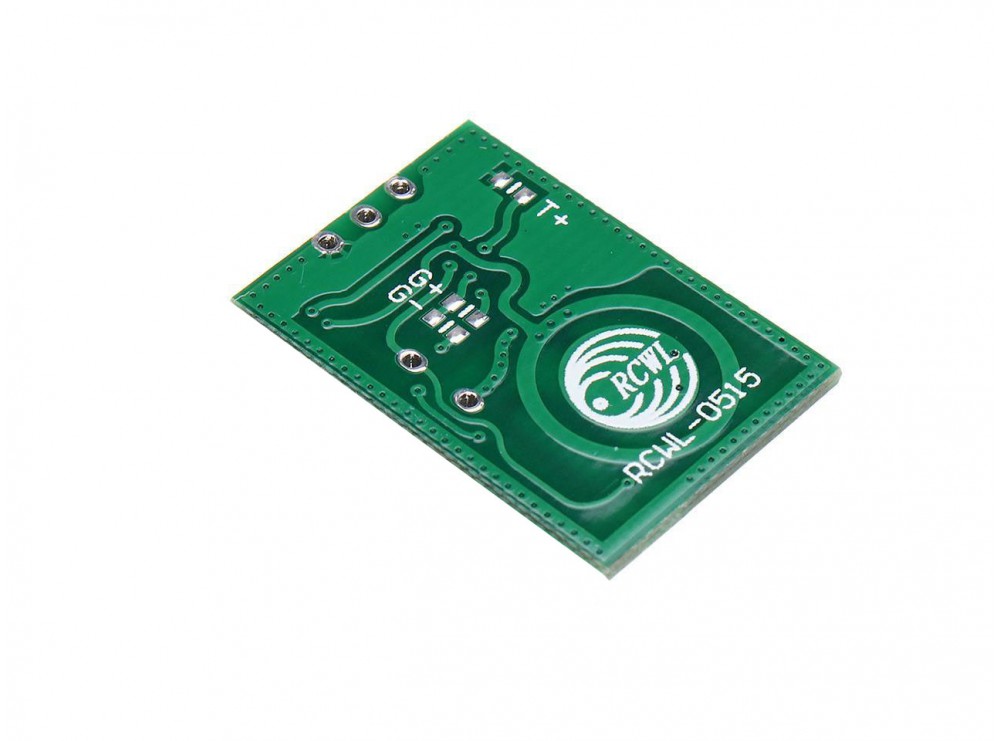
Oh my! What an interesting design that PCB is!
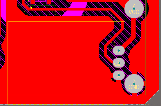
It looks to me as if the copper ring on the bottom of the board is actually used as a resonator, which, together with the FET on top of the middle of it forms an active oscillator. The circular patch (with the company logo) in the middle on the bottom would then form the actual antenna, and looking at the two feed vias, it's circularly polarized.
So,
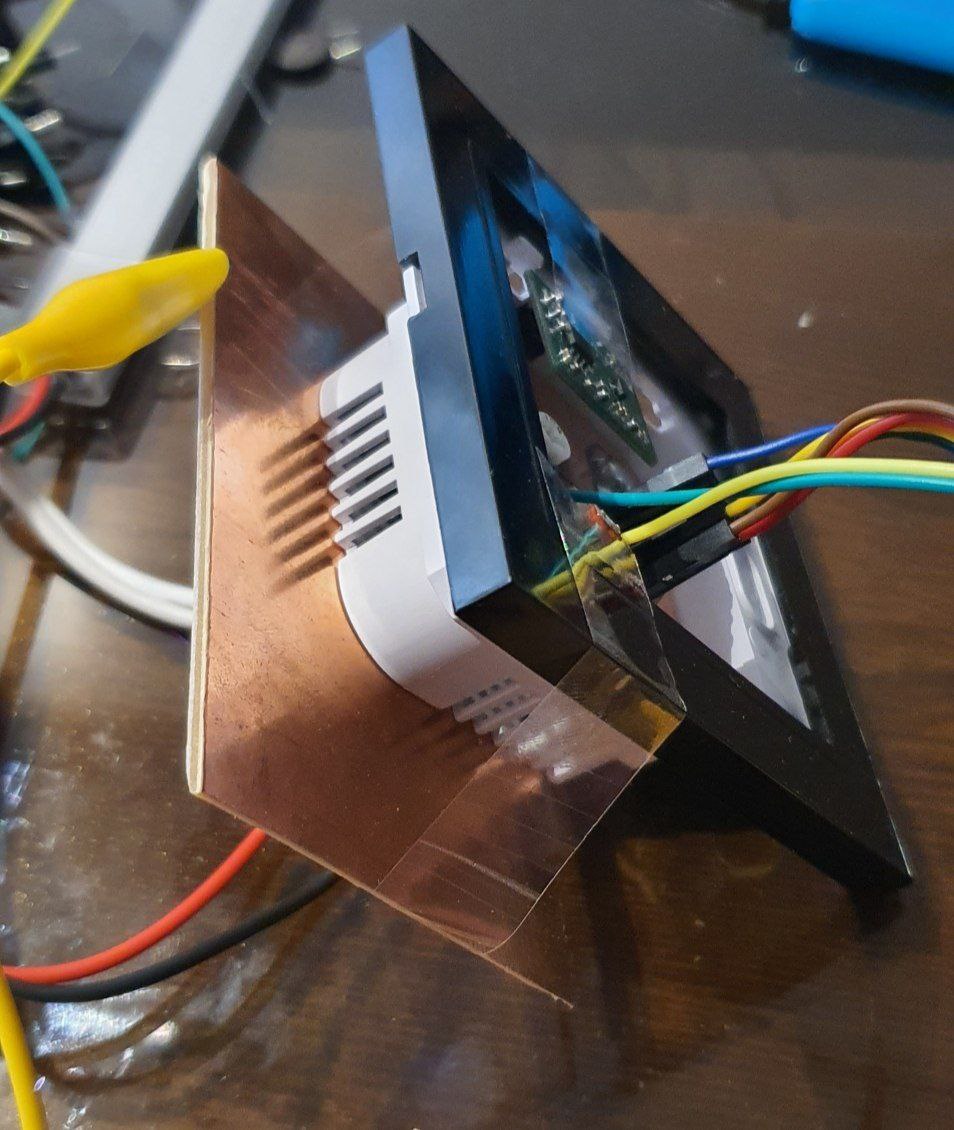
The only thing that comes to my mind and I haven't tried is to reduce the distance between the module and the board
that would most likely only succeed in detuning that resonator.
Your radar (and that's what this is, at least if we're a bit lax on the "ranging" part) is plain quite sensitive; it probably works happily through the multipath reflections that occur (nearly losslessly) on your copper plane and then your environment.
You have to face the fact that this device was meant to be sensitive to movement in the general environment – the patch antenna that's smaller in diameter than the resonator is long is a testament to "we don't want this to be very directive".
In all honesty, a different sensor board might be the cheapest and easiest solution; everything else will, in the end, involve microwave engineering, expensive (think: house-it-stands-in-priced) measurement equipment, or much trial and error.
You can put your whole sensor system in a closed copper-clad box, and by the design of slits in that box couple out the energy into a waveguide and finally an antenna of the directivity you want (or go for slit antennas). Or, you could try to design a near-field "antenna" that you put on the circular patch that's very good at coupling the RF out of that near field, and use that to feed an antenna of your choice, but:
- that antenna will necessarily be much larger than the on-board patch to achieve that directivity,
- all of this will require quite extensive design, and FEM RF modelling,
- both approaches will in first prototypes most probably work suboptimally and reflect too much energy back into the system, deafening it, and possibly even destroying the receiver.


