5
\$\begingroup\$

We are hoping to run i2c sensors at about 10 meters and add some sensors over CAT6a cable.

After doing some research, it looks like the LTC4311 can allow this, but it looks like the PCA9515A does something similar. (The PCA9515A can do bus-voltage translation, ie 3.3v to 5v, but voltage translation is not what this question is targeting).

Questions:

  1. For the purposes of overcoming bus capacitance, are these two components functionally the same in the sense that they accelerate the rise of the i2c signals?

  2. If they really provide for different use cases, why would you use one over the other?

  3. For wiring purposes, do you simply wire the buffer device close to the i2c master?

  4. Do you need a buffer on the device-end of the cable, too, or just one near the master?

\$\endgroup\$
7
  • \$\begingroup\$ My counter-question is, if you need to pass I2C over 10 meters of CAT6 cable, is there a reason why it would not work as-is, without these chips? \$\endgroup\$
    – Justme
    Commented Sep 5, 2023 at 19:48
  • 1
    \$\begingroup\$ @justme: 46pF/m at 10m =~ 460pF >400pF, and that's before wires flying and unexpected pF coupling everywhere. \$\endgroup\$
    – KJ7LNW
    Commented Sep 5, 2023 at 20:52
  • \$\begingroup\$ OK, I'll again have to ask, what is so magical about 400 pF (other than it's an arbitrary limit set by I2C specification, and you seem to want to use tricks to still work with capacitance that is over the limit, and tricks are already needed beyond 200pF. And the capacitance limit is a rating to allow maximum rated frequency. Simply use slower frequency and you can have more capacitance. Maybe I should add this to my answer?). \$\endgroup\$
    – Justme
    Commented Sep 5, 2023 at 21:04
  • 2
    \$\begingroup\$ @Justme, I guess NXP decided that 400pF is magical...but you're right, slower clock might work, too. I've not tried, just doing research at this point to make it robust. \$\endgroup\$
    – KJ7LNW
    Commented Sep 6, 2023 at 0:45
  • 2
    \$\begingroup\$ Related: electronics.stackexchange.com/questions/678578/… \$\endgroup\$
    – jpa
    Commented Sep 6, 2023 at 16:38

3 Answers 3

6
\$\begingroup\$

These two ICs are not equivalent in functionallity, although they serve a similar purpose.

PCA9515A is a repeater, as you would imagine a repeater to work. Signal input on one pin, signal output on another pin. With the bidirectional I2C that becomes a little bit more complicated, as the IC has to make sure to not go into lockup, but it is a repeater nevertheless.
You use it to to split a large I2C bus into two (preferably similar sized) chunks, each with about half the overall bus capacitance.

The LTC4311 on the other hand is used as a supplement to the pull up resistors. When the chip detects a rising edge, it supplies additional current to the bus capacitance, to increase the slew rate and charge up the bus faster. This enables to use of a larger bus (meaning larger bus capacitance, due to more connectes devices and / or longer traces).

To directly answer your questions:

  1. I guess yes, both act to accelerate rise time with large buses.
  2. The LTC4311 seems a more flexible solution to me. The PCA9515A comes with limitations, e.g. it can't support clock stretching by the slaves. The PCA9515A seems to me to be a good solution only when you have a situation with something like two seperate PCBs with an overall capacitance > 400 pF. By placing the repeater in the middle you basically have two smaller buses.
  3. No, the buffer should not be connected close to the master, but pretty much in the physical middle of the bus. You want to devide bus capacitance in two similar chunks.
  4. As already mentioned in the answer to question 3, don't place the buffer near the end of the cable, but in the middle. You actually can't use two buffers in one bus! The datasheet mentions, that due to slight variants in input and output levels (necessary to avoid lockup) only one repeater per bus can be used.
\$\endgroup\$
3
\$\begingroup\$
  1. No, they are very different. The other one accelerates the rise time of a single bus section by feeding extra current. The other allows to split a bus into two sections where capacitance of each section will not affect the other section and each bus section must only handle the capacitance of that section instead of both sections.

  2. Which chip to use, if any of them, depends on in which situation you are in, or can you design the whole bus or bus sections to allow use of one of the chips. It depends on the other chips you have. It might not even be possible to use the PCA9515 if your other chips depend on features not supported by PCA9515.

  3. Again it depends. As the PCA9515 splits the bus into two, it makes little sense to put it right near the master, as all the bus capacitance is still on one side. As the LTC4311 just accelerates the whole bus, it does not matter much where it is on the bus.

  4. You can't put two PCA9515 devices on same bus. You can use multiple LTC4311 chip on same bus for stronger rise time acceleration, but they all affect the same bus, so it does not matter where they are.

EDIT:

I2C does not limit you to 400pF. The standard has a chapter how to manage higher bus capacitance. The 400pF maximum limit is when you use the maximum clock frequency at maximum pull-up current. And even the full speed of 400 kHz Fast Mode standard is not possible with simple resistor pull-ups if capacitance is more than 200pF. One simple option is, if you have high capacitance, just decrease the clock speed.

\$\endgroup\$
2
\$\begingroup\$

With I²C, the speed of rising edges is limited by the low-pass filter that is formed by the pull-up resistor and the bus capacitance. The I²C specification limits the total bus capacitance to 400 pF and the pull-up current to 3 mA.

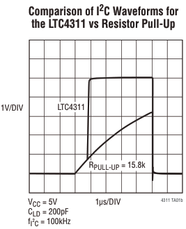
  1. They are quite different. The LTC4311 accelerates the rising edges, compared to a resistor, and thus allows faster speeds or a larger bus capacitance with the same pull-up current. (In the image below, the resistor is much weaker than what you would typically use in an I²C circuit, but in any case, the LTC4311's current source avoids the slow-down when the voltage gets higher.) The PCA9515A does not accelerate anything by itself, it just splits the bus into two segments so that each segment has a lower capacitance than the entire bus.

    LTC4311 waveforms

  2. The primary purpose of the PCA9515A is level shifting. You can also use it as a buffer, in which case the effect (faster rising edges due to lower capacitance in each segment) is somewhat similar to that of the LTC4311.

  3. It does not matter where on the bus you place the accelerator (or the pull-up resistor); the voltage on the entire bus must fall or rise, and at I²C speeds, the propagation delay is negligible. When using a buffer, you should place it in the middle so that each segment has a capacitance that is not too high.

  4. It is possible to use multiple buffers (but not the PCA9515A; always check the datasheet) so that you have three or more segments. This might be necessary to avoid having any segment with more than 400 pF (this is likely with your 10 m cable).

There are buffers that also have a built-in accelerator (e.g., TCA9803). They have the same effect as when you would combine the PCA9515A with the LTC4311.

\$\endgroup\$
1
  • \$\begingroup\$ Minor addition; the I2C limits the total bus capacitance to 400 pF and pull-up current to 3mA, if the bus is used at highest specified frequency. The I2C bus specification has a whole chapter about how to operate above the maximum allowable bus capacitance. You can have more capacitance if you slow down the bus clock frequency to allow for signal high and low times to be within specs. \$\endgroup\$
    – Justme
    Commented Sep 5, 2023 at 21:20

Your Answer

By clicking “Post Your Answer”, you agree to our terms of service and acknowledge you have read our privacy policy.

Not the answer you're looking for? Browse other questions tagged or ask your own question.