Don't.
First, shielded cable is required. I2C is a two-line, single-ended interface. It has a high impedance, and a low logic threshold voltage, so it is very susceptible to ambient noise in both the high and low states. Finally, it's edge-triggered (minus a small spike-filtering period of 50ns or so), ensuring that any line corruption also causes data corruption, and at the very least an error-retry or repeat-transmission or write-verify operation will be desirable, if possible at all.
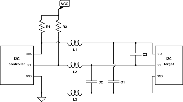
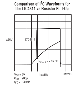
Second, cable length is limited by total bus capacitance, which will be way out of spec here. Stock I2C is just straight out.
There is differential I2C, using converters; this resembles RS-485 or CANbus in terms of signaling, with a 3.3V (or whatever) differential signaling and more consistently low impedance (terminated 100 ohm lines). This tolerates more line length thanks to the resistance swamping cable capacitance, but it only marginally solves the noise problem: instead of a ~0.5V noise margin, it's roughly the supply (~5V).
(I've heard some controversy over this "theory", of what the limiting range of differential I2C is. Datasheets don't specify input common mode range, but input voltage range specs suggest clamping diodes, indicating a hard limit at the supply voltage, even if the input differential detection range extended beyond the supplies. I've yet to see a contradiction to this -- if you have such information, please add it in the comments, I'd love to know more about these devices!)
(There is also the temptation to believe "it says differential, it must be differential!", which I think is all too common, and just a result of not knowing better. We even see symptom of this in the PCA9615 datasheet itself. My counter to this: "how differential?" Any device in existence has some CMRR, and CM limit, whether that's the input range or supply voltage, somewhat beyond (e.g. RS-422's -7/+12V range even for 3.3V devices); or even if it's fully isolated -- Ethernet for example still only has a 1.5kV rating, and much less at high frequencies due to the ESD capacitor.)
In any case, I would expect differential I2C to be marginal in a commercial setting, i.e. 3V conducted, 3V/m radiated immunity. It should be fine at 1V or so, but may encounter errors beyond. Some filtering (CMCs are applicable here) may be able to extend it to 10V.
I would strongly encourage using shielded differential pairs (connect shield to circuit ground at both ends) to avoid the above questionable range; and, with good quality shields (metallic connectors, enclosures, etc.), you can probably get 50V+ of immunity this way. Kind of overkill if you just needed a few more volts of immunity, but sometimes that happens, too.
The above also covers the use of CAT-5: preferably, don't; or, use shielded twisted pair (STP) instead.
Shielding also vastly improves ESD immunity, enough that the system may remain operational under such conditions; whereas without, it most likely causes data corruption, or a power cycle is required to reset it.
Note that typical devices do not offer much ESD immunity, so external clamp diodes are strongly encouraged.
As for range, check the specifications and supporting information / application notes of the differential interface you choose (e.g. PCA9615). Curiously, I don't see much of any recommendation offhand, but I see users claiming operation out to 30m or so.
Anyway, third: supply consumption. The SCD4x specifies peak supply consumption up to 205mA. Beware of cable resistance, and ensure adequate supply at maximum current consumption and maximum supported distance. If you have spare pairs (e.g. Cat 5), you can use them in parallel for supply, doubling the usable range due to resistance limit.
The datasheet doesn't specify duration of that current draw unfortunately, though comparing to the periodic mode specs, it may be on the order of 500ms. Possibly, a local bulk capacitor could be paired with the sensor to supply some of this charge, but quite a large value would be needed (10s, 100s mF?). Better: use an excess supply voltage (e.g. 6-12V) at the connector, and use a 5V LDO for each sensor and interface chip.
Finally: what is a preferred solution, then?
I would recommend asynchronous serial (UART) over RS-422, via local MCU. If the sensors don't need any input (other than startup, provided by the MCU), merely two pairs will suffice (power and SDO+/-), and UTP (unshielded twisted pair) will be suitable (which includes two-pair cable e.g. Cat 3 and other types). Otherwise, 3 or 4 pairs for power (1 or 2 in parallel), SDO+/- and SDI+/-.
UART communications are not restricted by delay in any way (at least, not in and of themselves; typical protocols are extremely relaxed about timing), allowing up to the full ~km limits of RS-422 if you really needed it (of course, a local supply, or a more aggressive remote-power solution like say 48V plus a converter, will be needed then). Baud rate can also be quite high even over such distances (and to the point, higher than dI2C's limit), if that should be valuable. For this kind of sensor of course, quite low baud could be selected, gaining further EMC immunity by filtering lower.
And yes, this is a bother. That's more MCUs you need to buy, and place, and program. They only need to be programmed with one thing, once, of course (assuming you make the sensors either identical, or sufficiently general that they are compatible over whatever overall protocol solution you've employed), and low-performance MCUs can be quite cheap (a tinyAVR, or PIC, or STM32F0, or... would be more than sufficient).
(You may also want an additional MCU to coordinate the hub / router as well. Or perhaps choose a different topology: using RS-485 for example, with a suitable addressing or priority system, a single pair can be used for bidirectional communication over a common bus of devices all in parallel. Even better: use CANbus proper!)
Final note: if cross-wiring might be a concern, don't use 8P8C connectors that might get confused for Ethernet. Pick something else. Even just, various kinds of headers, will be acceptable for RS-422 (with suitable filtering in place to account for the unshielded length near the connector(s), and preferably with the shield connected through multiple pins across the header), or automotive or circular types may be attractive for compactness and environmental immunity (IP6x ratings, say).
Additional reading: I2C differential network architecture using PCA9615


