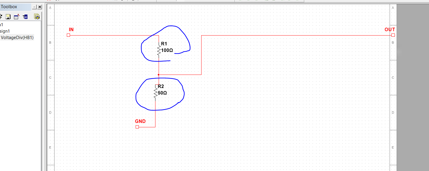
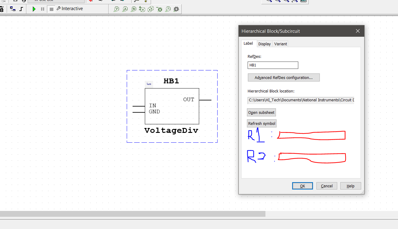
I can't tell you about Multisim, since I don't use it. But here's how LTspice handles parameterized hierarchical schematics.
First, a little documentation from LTspice about hierarchical schematics, generally:
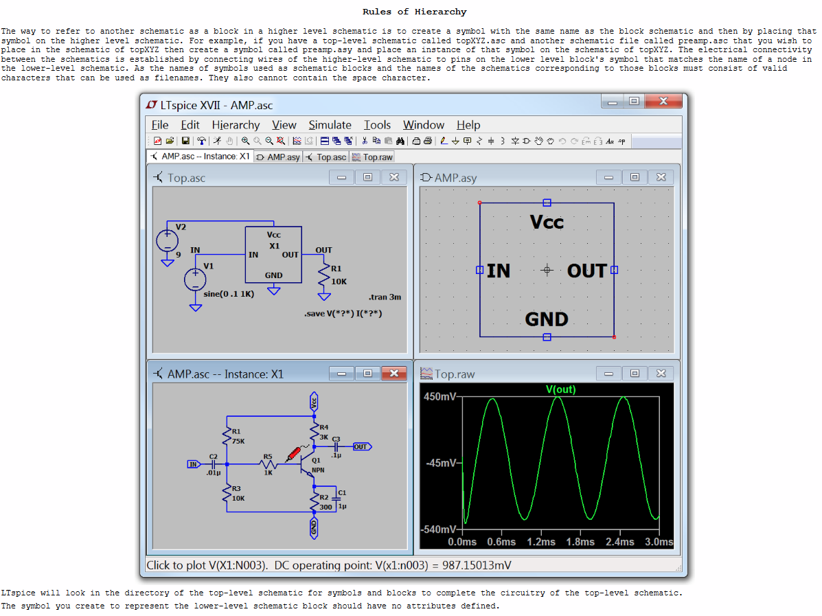
Now, for parameterizing these things, Spice's .PARAM card can be used on a lower-level schematic to create a modifiable parameter/variable. And at least in LTspice, you can then modify it in the higher-level schematic as a way to over-ride and control it.
So let's call the following lower-level schematic as DIVSUB.ASC in an LTspice schematic directory:
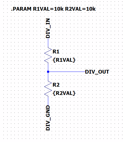
I then edit and create a symbol in LTspice that I can use for it and save that in the same directory with the lower-level schematic. In this case, something like this:
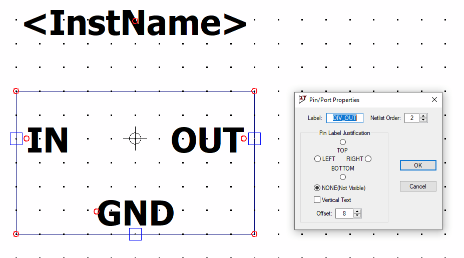
In the above case, I also show a dialog box for the output pin -- note that the LABEL in the dialog box there matches up with the label I used in the lower-level schematic. (Ignore the text I place on the symbol itself. That's just text that the user sees when the symbol is being placed on a higher-level schematic.) The same consistency in naming was also done for the other two pins. This allows LTspice to associate the symbol pins with the lower-level schematic node names so that the two know about each other.
Then I can use this new symbol on a new higher-level schematic:
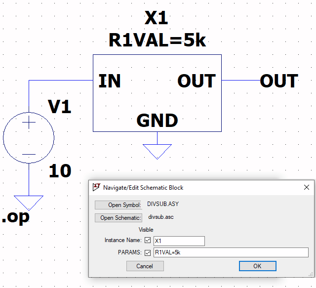
Note that LTspice provides a dialog box that allows me to over-ride specific .PARAM values in the lower-level schematic and that it displays that over-ride.
Let's create two of these, one without over-ride so that the defaults are used and we expect to see half the input voltage at the output and one with the \$5\:\text{k}\Omega\$ over-ride where we expect to see a higher value:
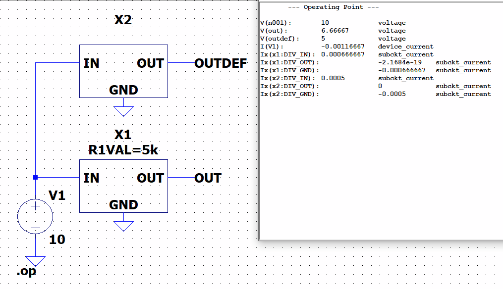
Here's the netlist that was generated for the above:
V1 N001 0 10
XX1 N001 OUT 0 divsub params: R1VAL=5k
XX2 N001 OUTDEF 0 divsub
.subckt divsub DIV_IN DIV_OUT DIV_GND
R1 DIV_IN DIV_OUT {R1VAL}
R2 DIV_OUT DIV_GND {R2VAL}
.PARAM R1VAL=10k R2VAL=10k
.ends divsub
You can see the two "X" devices (.SUBCKT function calls) as well as the auto-generated .SUBCKT that was drawn from the lower-level schematic and created on the fly by LTspice. The fact that LTspice can do all this means that the netlist can be ported to other Spice programs, directly, without needing to separately carry along the referenced schematics. The top level schematic contains everything needed to run it.
And there it all is.
Multisim may have a similar approach that you may need to look for in the docs.

