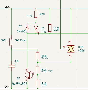
I am reverse engineering a toaster.
I have the following part of the circuit that I don't understand.
Let me explain what I have at the moment:
We have a potential difference of around 20V DC coming from a divider bridge in the toaster followed by a rectifier diode and a smoothing cap.
Pressing the button lights the led up and activates something in the timing circuit. After releasing the button the function is kept in memory using the 4066 and the led still shines.
Now what does not make sense for me is that the divider \$R_{16} / R_{13}\$ gives for the transistor \$V_{be}\$ at around \$4V\$
Bonus questions :
- What is the point of \$R_{19}\$?
- Why not driving the LED by current?
I may have done some mistakes doing the schematics. I am pretty sure of resistors value and confident about the wiring because there is exactly the same circuit for an other switch button. I made them independently to double check.
I unfortunately don't have access anymore to the board.
Sorry, it looks more like a puzzle than a ESE question.

