4
\$\begingroup\$

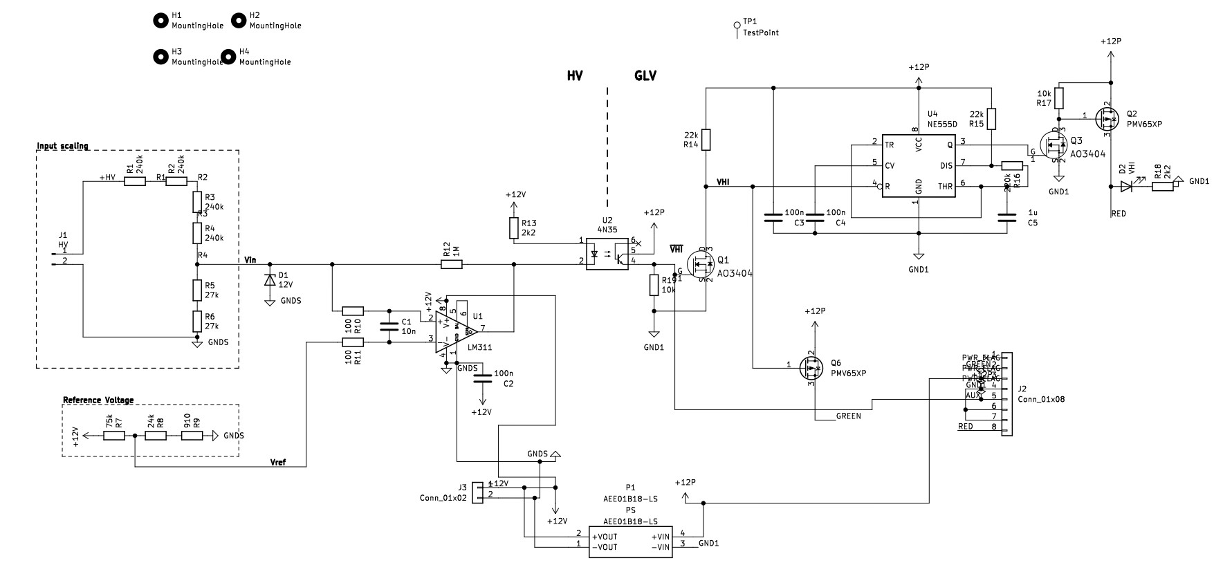
This schematic was created for an FSAE prototype car, in order to be used to detect if HV is present. It's called the TSAL (Tractive System Active Light), and I based most of the design from YouTube.

Kicad schematic

I got the PCBs manufactured and everything works fine, apart from the LM311.

The HV connections aren't connected yet and the non-inverting (pin 2) input is pulled low through R5 & R6. The reference voltage is stable at ~3V. I would expect the LM311 to pull-low at the open-collector (pin 7) and drive the optocoupler. The output is low (~900 mV) however, the LM311 is not sinking any current. Instead it heats up by itself to 60-70°C (painful to touch by hand).

I received a batch of 5 LM311 ICs, and all of them behave the same way. I've tried testing the ICs independently on a breadboard, by also making the non-inverting input > inverting input. The output stays low (~900 mV which doesn't make sense). However it doesn't get hot this time. The comparator is not oscillating and the output is stuck at ~900 mV.

Seems like all the ICs are shorted internally which is very strange. Am I doing something stupid here?

More details

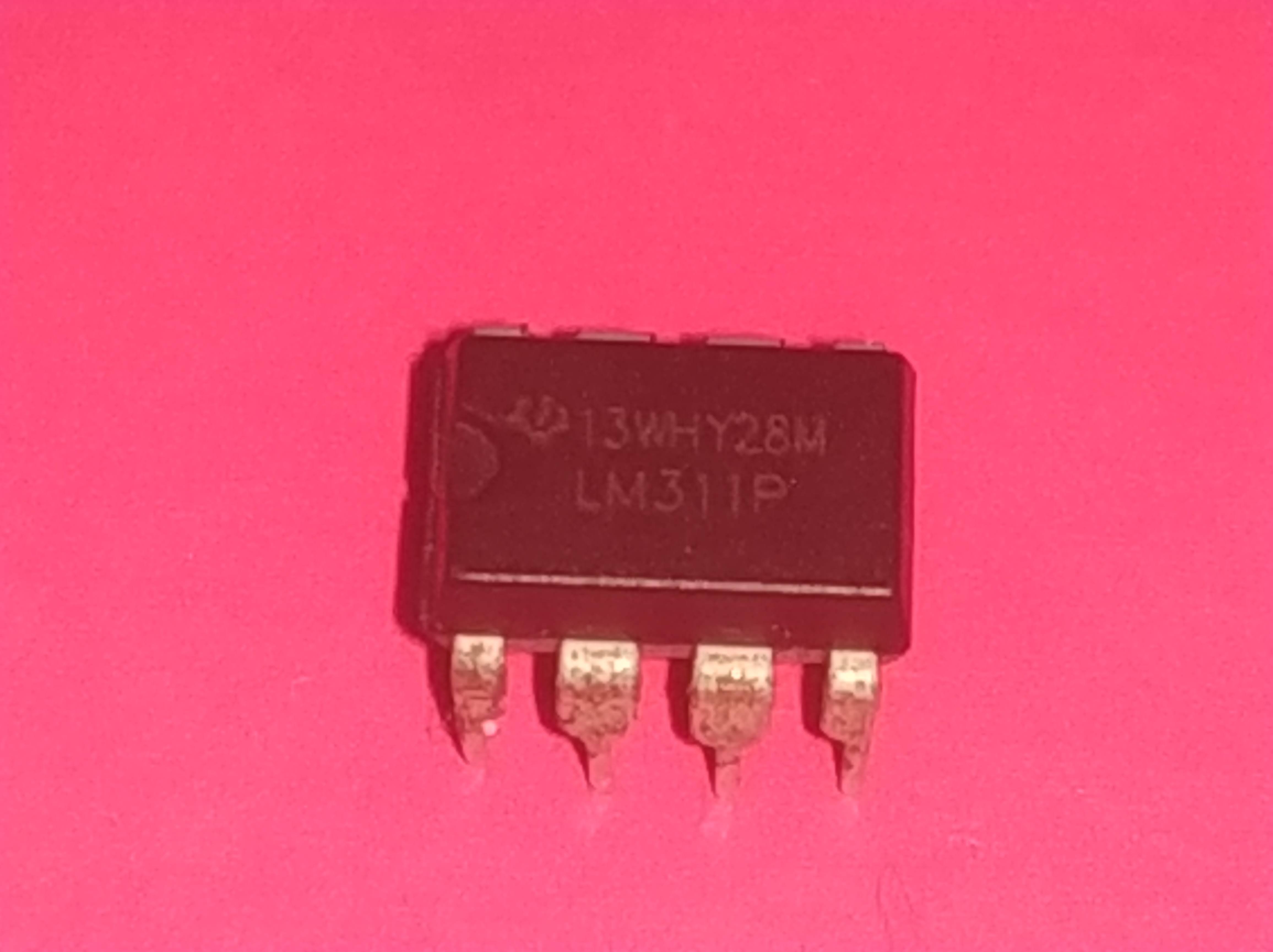
Here's a pic of the PCB layout PCB enter image description here And here's a pic of the individual IC enter image description here
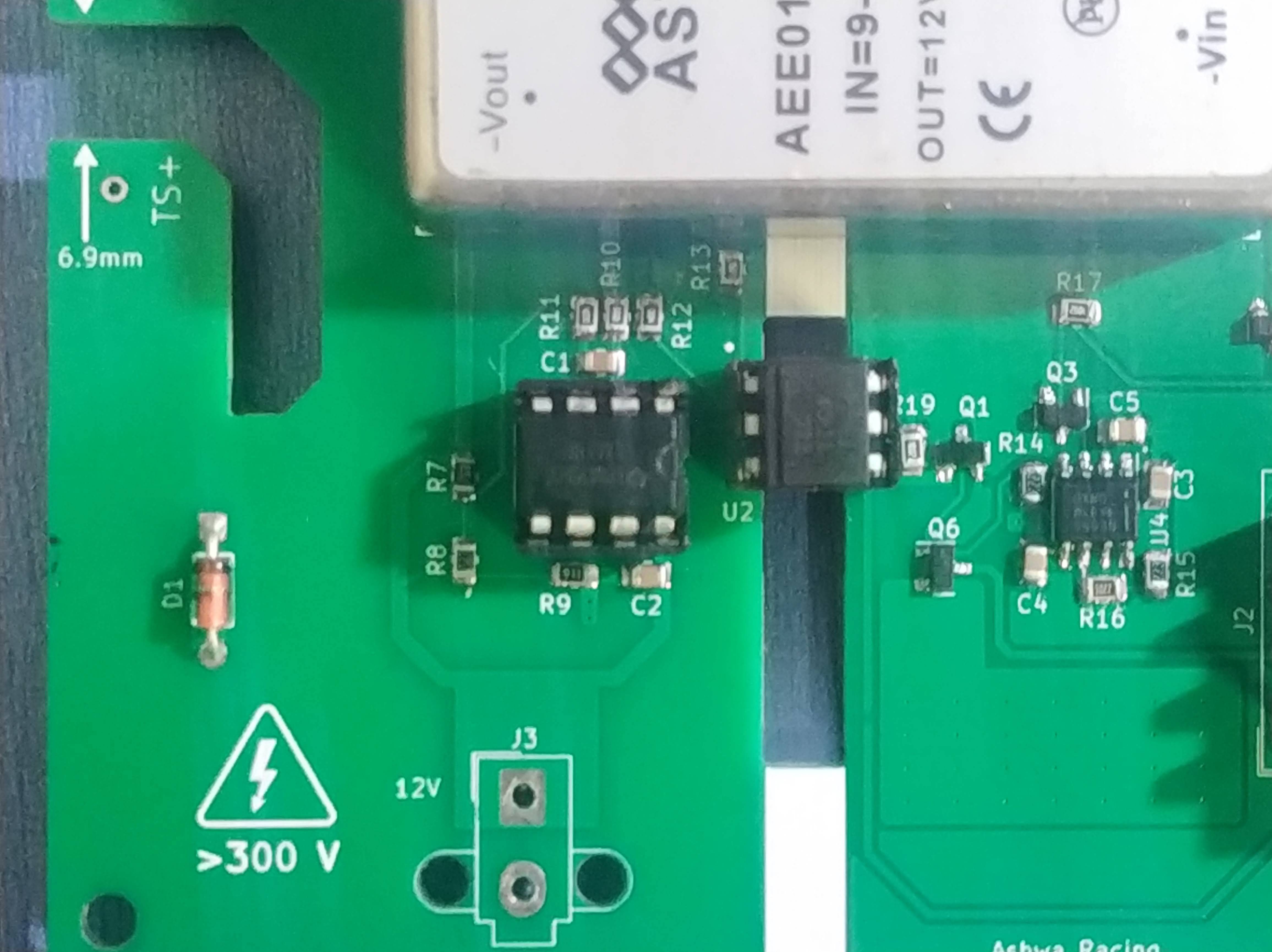
I bought all 5 ICs locally through a retailer (like radio_shack kinda).

\$\endgroup\$
9
  • 1
    \$\begingroup\$ what do you expect your "high voltage" to be, and what produces it? \$\endgroup\$ Commented Oct 21, 2023 at 21:32
  • 1
    \$\begingroup\$ Where did you buy them from? If anywhere but a reputable distributor, they are likely to be counterfeit or factory rejects. Please also post a photo of the ICs, as well as your implemented circuit (breadboard or PCB photo) \$\endgroup\$ Commented Oct 21, 2023 at 22:16
  • \$\begingroup\$ @TomCarpenter I bought them locally since that's the quickest way for me. It's a pretty famous shop and I haven't had any issues with their parts untill now \$\endgroup\$
    – BHU1 LORD
    Commented Oct 22, 2023 at 5:43
  • \$\begingroup\$ @MarcusMüller The HV is the accumulator voltage of the FSAE electric car. ~300VDC (6.8 kW) \$\endgroup\$
    – BHU1 LORD
    Commented Oct 22, 2023 at 5:45
  • 2
    \$\begingroup\$ @BHU1LORD - Hi, Please don't modify the question (including title) to give the answer. However it's completely fine that you posted more details as a self-answer, when you have new information about the solution (as happened here). Thanks. (I have reversed your edit and then improved the original title.) \$\endgroup\$
    – SamGibson
    Commented Oct 30, 2023 at 18:56

3 Answers 3

2
\$\begingroup\$

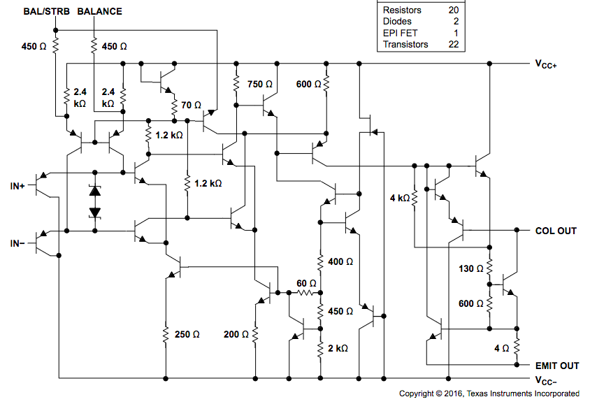
To check if it could be a fake IC you can do some basic tests with the multimeter. I have some LM311's and they seem to match. You can look at the diagram in the Texas Instruments LM311 datasheet:

Functional block diagram from LM311 datasheet

With a multimeter in the position to measure diodes voltage drop and the IC out of the PCB, you should measure about 0.7V between Vcc- and IN+ and between Vcc- and IN- (pins 4,3,2). That's the expected voltage drop of the junctions of the BJT's in the diagram. The same from Vcc- to COL OUT.

You can also measure the resistances between BAL/TRB - Vcc+ and BALANCE - Vcc+ pins. I measure less ohms than in the diagram, I suppose that because there is some other resistance path in parallel.

This is not a definitive prove, the chips can still be damaged, or maybe there are others with similar design, but at least can help to identify fake ones.

\$\endgroup\$
6
  • \$\begingroup\$ "With a multimeter in the position to measure diodes voltage drop and the IC out of the PCB, you should measure about 0.7V between Vcc- and IN+ and between Vcc- and IN- (pins 4,3,2). That's the expected voltage drop of the junctions of the BJT's in the diagram. The same from Vcc- to COL OUT." ----> All of this worked out I see 0.7V across all base-collector junctions. BUT the BALANCE and BALANCE/STRB pins have no resistance to VCC+ on all ICs. Maybe this is the nail in the coffin. Anyway I'm getting a new batch of 5 from a different supplier, let see \$\endgroup\$
    – BHU1 LORD
    Commented Oct 22, 2023 at 7:31
  • 1
    \$\begingroup\$ Maybe they are damaged. In my case between BALANCE or BAL/STRB and VCC+ I measure about 2KΩ, instead of (2.4K + 450)Ω. \$\endgroup\$
    – Gos
    Commented Oct 22, 2023 at 7:38
  • 1
    \$\begingroup\$ @BHU1LORD "Anyway I'm getting a new batch of 5 from a different supplier". Forget Ebay and batches of 5. Try a reputed electronics shop or even an authorized distributor like Mouser or Digi-Key or Arrow Electronics. \$\endgroup\$
    – user107063
    Commented Oct 22, 2023 at 9:50
  • \$\begingroup\$ I got screwed again, I had bought another batch of 5 even before I wrote this question. Turns out none of these new ones also have the 2k res. Im thinking all these fake ICs are LM358's (or some other dual op amp) die in a LM311 DIP 8 package. Should have listended to you @user107063. Anyway after wasting some money and some hours trying to debug, Im buying these from mouser itself \$\endgroup\$
    – BHU1 LORD
    Commented Oct 30, 2023 at 18:24
  • \$\begingroup\$ What I do is wait until I have several components to order to mouser, up to 50€. Otherwise I have to pay about 20€ for the shipping. Meanwhile if I need something I order it in Aliexpress but to 3 or 4 sellers at the same time that look less suspicious. The ones that are fakes I get the money back inmeditaly without questions. This way I have some chances to get some working ones to start prototyping. \$\endgroup\$
    – Gos
    Commented Oct 30, 2023 at 19:07
5
\$\begingroup\$

The mystery has been solved, turns out all these fake LM311s are actually LM358s in disguise. Here's how I figured it out

  1. EEVBLOG Mislabeled LM311 and Youtube Beware of fake LM311's on eBay!
  2. Based on this I saw the issue with my schematic and the fake IC. In an actual LM311 the IN+ is pin 2 and IN- is pin 3. This is reversed in LM358. In my schematic the output emitter pin (pin 1) is connected to GND. If this IC is actually an LM358, whenever the voltage on pin 3 > pin 2, pin 1 (output of the first op-amp) is pulled high. This shorts the op-amp1 to ground and basically overheats the IC (my supply was current limited to 2A, however I haven't measured the short circuit current.)
  3. Pulling supposed BAL/STRB pin low, turns pin 7 high even with no pull-up resistor on collector.

I don't know why this is even a thing because even the original LM311 isn't an expensive IC to begin with. Lesson learned.

\$\endgroup\$
1
  • 1
    \$\begingroup\$ Sometimes it is a matter of availability. Lots of older designs, in particular in DIP form factor, are getting retired by the manufacturers, and old stock, well, runs out of stock sometime. If a part isn't available at the main distributors any more, stores run out comparatively soon and the desire to secure some of the remaining stocks then powers up the counterfeiting floodgates that dilute the remaining parts to uselessness. \$\endgroup\$
    – user107063
    Commented Oct 30, 2023 at 18:52
2
\$\begingroup\$

For single opamps/comparators, a favorite basis for counterfeits is the ubiquitous µA741 or LM741. It is, however, not even pin-compatible with the LM311 so it would be rather stupid to use as a counterfeit source.

When used as replacement for more expensive single opamps that are pin-compatible, it can be distinguished by its operative offsetting pins 1 and 5 that measure as slightly below 1k resistance from V- at pin 4. This is one way to tell an LME49710 (for example) from an LM741 because the former does not have the offset pins connected internally at all. Several other high-quality opamps that have workable offset pins have different circuitry on them and measure differently.

It may be worth checking for this peculiarity in order to figure out whether you are dealing with a really stupid forgery here for generic "8-pin DIP single opamps/comparators".

That you have bought 5 equal chips from the same source makes it sound like you got them on Ebay: the normal discount pricing starts with 10, so why buy 5 if it hasn't been a specific offer for 5?

Apart from electric differences, other telltale signs of a forgery are the depth of any depressions on the IC top: after sanding off the original writing, the depressions tend to be at the shallow end of the case tolerance. Similar for overall case depth.

Of course there are also less ominous other explanations, like having placed the chip the wrong way round.

\$\endgroup\$
1
  • \$\begingroup\$ I also noticed that the ICs I bought dont have the Pin 1 circular indent, so a bit sketchy \$\endgroup\$
    – BHU1 LORD
    Commented Oct 22, 2023 at 5:50

Your Answer

By clicking “Post Your Answer”, you agree to our terms of service and acknowledge you have read our privacy policy.

Not the answer you're looking for? Browse other questions tagged or ask your own question.