I'm working on debugging a boot problem with an Atmel AT91SAM9G20 board. Everything goes great for the first 700 ms or so. It seems that about 700 ms after reset, the processor freezes. What's curious is that the CPU drives the reset line after I release the reset button.
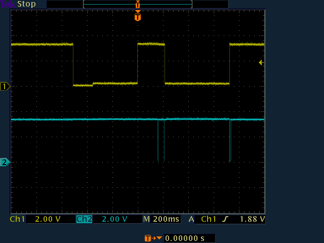
Here's a scope shot that shows what's going on. The yellow trace is the reset line. The first dip is the time I'm actually holding down the reset button. The second dip is, I believe, generated by the CPU.
The blue trace is serial data coming out of the CPU. The first two bursts come from the initial bootloader. The third burst is U-boot starting. The CPU stops sending out characters when the third blue burst ends.
If I'm interpreting the traces correctly, this means that the reset line is low for almost exactly the time that the processor is loading U-boot from NAND flash.

I have a few questions:
- Is this sort of CPU-controlled reset normal?
- Any suggestions about how to debug this?
A few more details: I should add that I've looked at the power rails, and they look clean. The behavior below is reproducible. I can vary the length of the initial reset dip (in yellow) by a few seconds, and the rest of the behavior happens the same way. If I plug in the JTAG cable, the behavior changes-- sometimes it boots, sometimes it doesn't, but after a few seconds, JTAG takes over, and the processor is halted.
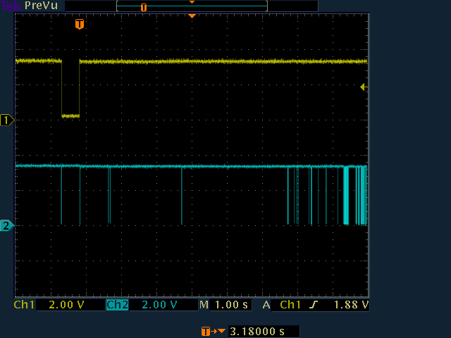
Under JTAG, I can boot successfully. Here's what a successful JTAG-controlled boot looks like:

Note that the timescale is different, and I'm not pushing the reset button-- it's software controlled. The same reset dip occurs. In both cases, the length is around 500 ms.
Update (still baffled)
Prompted by Mr. Taffey's suggestion below, I have investigated the watchdog timer and the reset controller in more detail. The watchdog timer is in fact disabled by the first bootloader; I'm pretty sure that code is being executed because it occurs before text is sent out the debug serial port, and I can read the text successfully.
In reading about the details of the reset controller, I learned that the processor is supposed to grab control of the reset pin and pull it low for a short period. This is to ensure that other hardware on the board listening to the same line receive a long enough reset. Digging through U-boot, I found that the duration of the reset was set to 0x0D using the ERSTL field:
at91_sys_write(AT91_RSTC_MR, AT91_RSTC_KEY |
  (AT91_RSTC_ERSTL & (0x0D << 8)) |
  AT91_RSTC_URSTEN);
The datasheet explains that the duration is set to 2^(ERSTL + 1) slow clock periods.
The reset duration looks around 500 ms long, the slow clock crystal is 32768 Hz, and Google tells me that log(0.500 * 32768) / log(2) = 14, and 0x0D + 1 = 14, so this all makes sense.
I think the real problem may be U-boot crashing; the fact that it happens just after this reset is probably irrelevant. What's confusing is why U-boot would crash only when JTAG is not connected.
Second update
I still don't know what's going awry or why JTAG makes it behave differently, but I think I have figured out a workaround (sort of). It looks like the U-boot crash is being caused in some way by the NAND flash on the board. By chance, the next revision of the board, which just arrived recently, uses a microSD card rather than NAND flash for bulk nonvolatile storage (well, there's NAND flash inside the microSD card, but you see the point).
My "solution" is just to start using the next revision of the board. U-boot also crashes on that, but for known reasons-- it is configured to look for a NAND flash, which it cannot find. Hence, it dies a fiery death.
So, problem "solved." (Expect another question shortly along the lines of "How do I make AT91Bootstrap load U-boot from a serial flash?" or "How do I make U-boot work with a microSD card?" or "Why am I doing this?")
I guess the green check mark goes to Joby for noticing that the reset line can be driven by the micro, even though it turned out to be irrelevant in the long run. Thanks for the help, all of you. I appreciate it.
Third update (about a week later)
I've been mostly working on other stuff recently, but I did figure out what the problem was eventually. My last mystery I summarized above as:
What's confusing is why U-boot would crash only when JTAG is not connected.
In fact, it turns out that I was mistaking U-boot failing to send characters out the debug serial port for U-boot crashing. I still don't understand the details, but I've discovered that it's not JTAG that makes U-boot work-- it's a common ground between my circuit and the USB host of my PC, which JTAG was providing, because it runs through the USB port. In fact, U-boot was working fine the entire time, but whenever JTAG was disconnected, the RS-232-to-USB level shifter I had breadboarded would stop working, the serial port would fail, and I would assume U-boot was dead. In reality, I discovered that I could, for example, still type ping commands and see the ICMP packets produced, even though my characters weren't echoed on the terminal.
I don't understand exactly what was going wrong, but I don't really care-- I can easily find another way to read the serial port, and in the short term, I can just make the connection to USB ground with a wire.
Thanks for the help, all.
