1
\$\begingroup\$

I am working on a controller based around the PIC16F18877 which will need to control a 4-wire 12V DC Fan, as well as read the signal from the sensor wire. The PWM signal needs to be somewhere between 18kHz and (I think) 30kHz, so I am planning on using a 20kHz. Since the MCU runs on 5V and the fan needs a 12V signal, I will obviously need some kind of level switching. Also, the signal will need to travel about 6-10 feet from the control unit to the fan.

I was doing some research online and found some conflicting information. Some sources said I should be able to run the fan directly from a MOSET, something like this: enter image description here
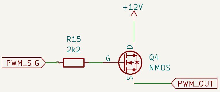
(NOTE: I forgot to add the pull-down resistor on the PWM_Out line for when the MOSFET is off)

However, other sources said about using a circuit similar to this: enter image description here
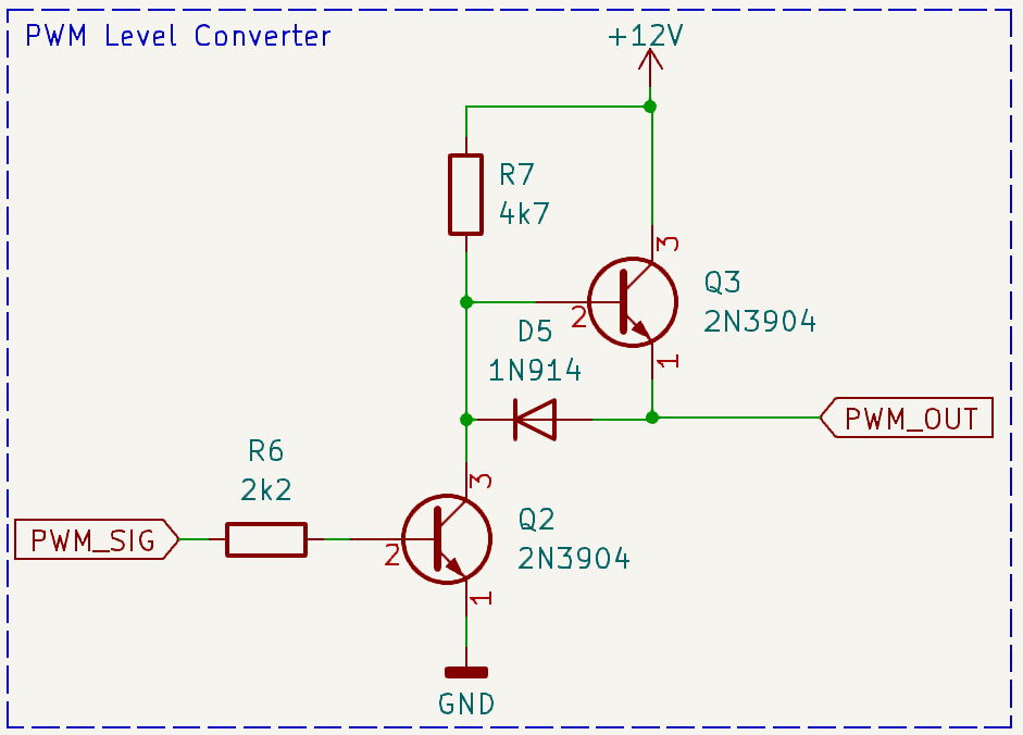
Can only suggest which one would be better and meet all my needs, specifically:

  1. 20kHz signal
  2. PWM_Out wire will be approximately 6-10 feet long
  3. PWM signal being generated from a PIC16F18877

Also, along the same lines, since I need to read the speed back, and convert the 12V signal from the fan back to 5V as an input to the MCU, whichever circuit I use to send the PWM signal to the fan, I am assuming I can just flip it around and use it in reverse, correct?

Any suggestions/guidance would be appreciated. TIA.

\$\endgroup\$
2
  • \$\begingroup\$ You need to peek at the analog characteristics of the transistor used. Or it might not toggle fast enough for your needs. \$\endgroup\$
    – Lundin
    Commented Nov 9, 2023 at 14:15
  • \$\begingroup\$ Are you sure the fan tachometer signal isn't open-collector? \$\endgroup\$
    – vir
    Commented Nov 9, 2023 at 15:02

1 Answer 1

1
\$\begingroup\$

I would suggest using the following circuit:

schematic

simulate this circuit – Schematic created using CircuitLab

(1)

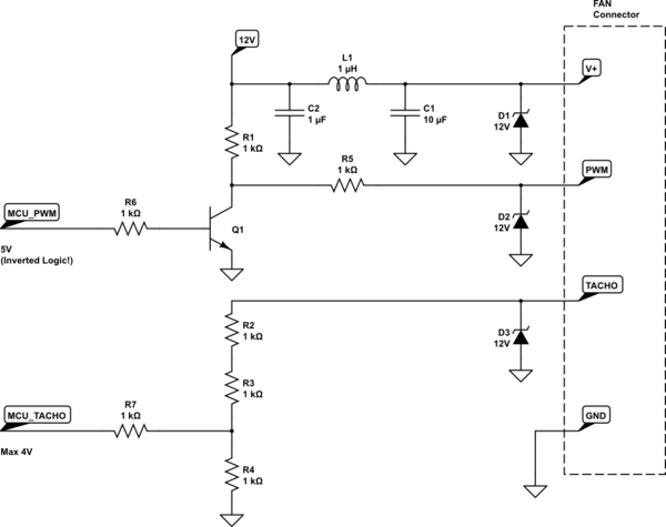
The Upper part in includes a CLC T-Filter for the V+ supply rail to decrease EMI-Coupling. As the fan is connected through a long cable, a TVS diode is added as well!

(2)

The PWM signal is level-shifted from 5V to 12V via a pullup resistor and a NPN-Transistor/FET. R5 is added to protect Q1 from EMI events. R6 should also be added if Q1 is a fet to reduce gate current peaks. Also D2 is added due to the long cables.

CAUTION: This circuit inverts the PWM logic - you have to take care in software.

(3)

The tacho signal is scaled to 1/3 * 12V ~ 4V by a simple resistor divider. You can increase the resistor values here, but i would go with 1kOhm to reduce the number of reels in assembly. R7 is added to further protect the MCU. The MCU (running at 5V) will be able to reliably detect a 4V signal as "HIGH". Also D3 is added due to the long cables.

NOTE:

This circuit will not produce a "perfect pwm with sharp corners and good rise-times". But, as your frequency is rather low, you shouldn't really care. Make your circuit simple and reliable - will work good enough.

But, there are also dedicated FAN-Controller ICs available for such applications! See as example

\$\endgroup\$

Your Answer

By clicking “Post Your Answer”, you agree to our terms of service and acknowledge you have read our privacy policy.

Not the answer you're looking for? Browse other questions tagged or ask your own question.