0
\$\begingroup\$

In this schematic (below) from the Texas Instruments UCC28250EVM-564 User's Guide (Controller for Half-Bridge DC-to-DC Converter With Secondary-Side Control), they use a bias winding. I understand that VCC is generated form Vin and it's 11V. This will power the drivers of the MOSFETs on the primary side. SecBias is generated on the secondary side, it is 8V, and it will power the controller.

What I don't understand is:

  • How is the winding 3-4 connected to the secondary? Is it through the winding 11-8? Are they connected in any way?
  • What is the role of Q3 and D7?
  • Why is there that connector for "Aux Start-up Bias input"? Is it just in case I want to connect an external power supply and skip the other circuitry when turning on the converter?

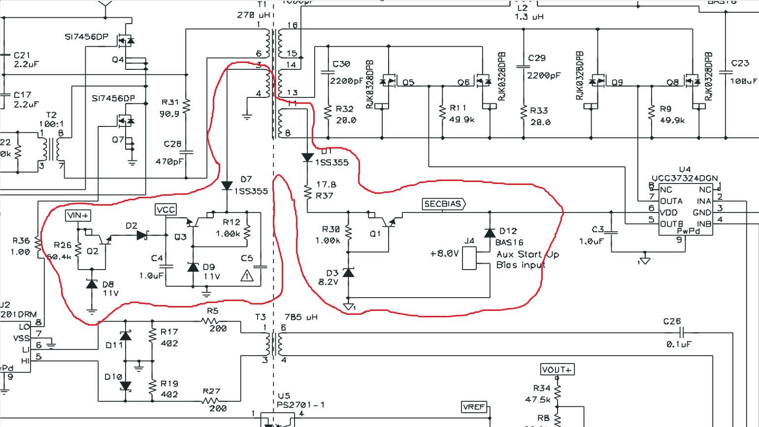
schematic

\$\endgroup\$
0

2 Answers 2

1
\$\begingroup\$

The 3-4 winding is not connected to the secondary in any way; that would defeat the purpose of having primary-secondary isolation.

D7 is a rectifier, and Q3 (in conjunction with D9) generates a very loosely regulated 12-ish volt Vcc supply.

The "aux startup bias input" appears to be for providing an alternative power supply on the secondary side to help the UCC37324 start up faster. It's not necessary, as the 8-11 winding on the transformer will provide power once the switching regulator gets going, but its presence will help the system start up faster.

\$\endgroup\$
2
  • \$\begingroup\$ So winding 3-4 is not coupled in any way to the secondary? Why isthe 12V regulation done twice in the primary side, once with Q2&D8 and then with Q3&D9? \$\endgroup\$
    – PosFLo
    Commented Dec 22, 2023 at 15:21
  • \$\begingroup\$ @PosFLo It's coupled, through the transformer. But it's not connected. Q2 and D8 are to regulate the input voltage, then Q3 and D9 provide a more efficient supply (at least, more efficient if Vin > 12 V) to reduce losses. \$\endgroup\$
    – Hearth
    Commented Dec 22, 2023 at 15:24
0
\$\begingroup\$

How is the winding 3-4 connected to the secondary? Is it through the winding 11-8? Are they connected in any way?

There are 5 windings on your transformer and, as a component, they are all galvanically isolated from each other.

What is the role of Q3 and D7?

Q3 is an emitter follower acting as a voltage regulator thus, the voltage on the base (set by the 11 volt Zener D9) ensures that the voltage at the emitter can't rise higher than about 10.3 volts.

D7 and C5 form a half wave rectifier and smoothing circuit that feeds Q3.

Why is there that connector for "Aux Start-up Bias input"? Is it just in case I want to connect an external power supply and skip the other circuitry when turning on the converter?

I don't expect it is needed but, it might be there to allow testing at lower AC supply voltages that wouldn't otherwise produce enough local voltage to enable the secondary synchronous rectifiers to work. Maybe scan through the document you got it from.

\$\endgroup\$

Your Answer

By clicking “Post Your Answer”, you agree to our terms of service and acknowledge you have read our privacy policy.

Not the answer you're looking for? Browse other questions tagged or ask your own question.