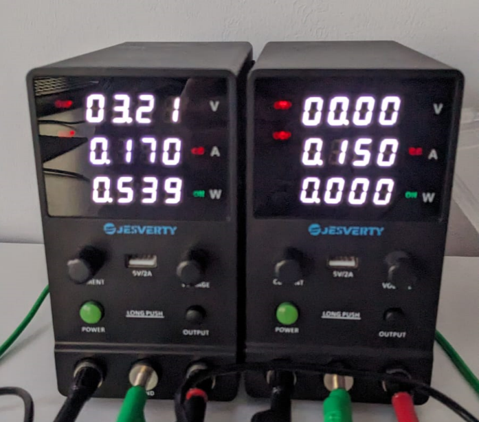
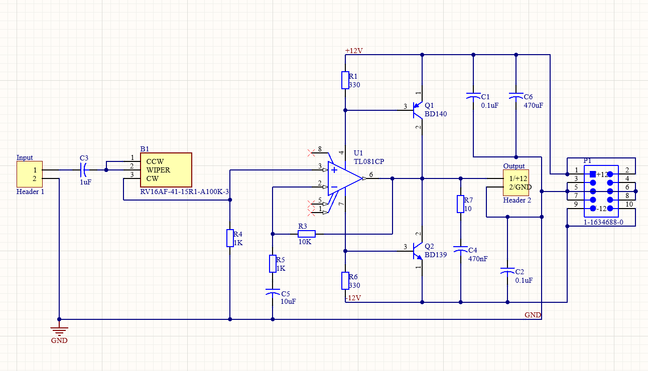
I designed a basic power amplifier powered by +12V/-12V. During the breadboard testing phase, the bench power supply indicated a stable voltage of +12V/-12V and a current draw of 150mA. After receiving the ordered PCB and soldering all the components onto it, I connected the power amp to my home bench. However, my home bench reached the current limit, and the voltage dropped to around 3.20V.

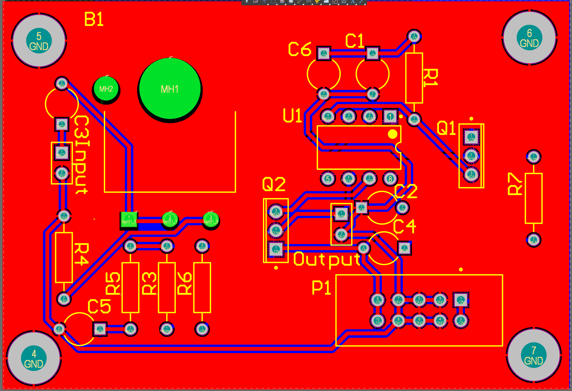
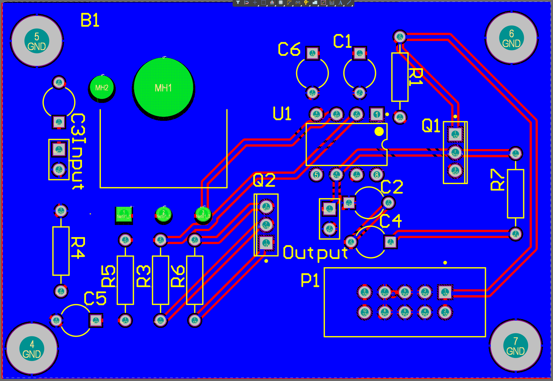
Despite using a multimeter to troubleshoot by placing one pin on the +/-/GND and probing through all other components with the second pin, I couldn't pinpoint the issue. I suspect that the problem lies internally within the PCB itself.
I would greatly appreciate it if someone could provide feedback on my schematics and highlight any design flaws I may have overlooked.
PCB: Top layer
Bottom layer


