2
\$\begingroup\$

In my circuit I have three op-amps in (direct) series connection:

  1. AD8422 acting as an input buffer (a large input impedance is needed) with a fixed gain (slew rate: 0.8 V/us)
  2. LTC6910 being used as a PGA (slew rate: 16 V/us)
  3. AD8476 acting as ADC driver for single-ended to differential conversion (slew rate: 10 V/us)

All op-amps have a +5 V to -5 V dual supply. I directly inject the following (single-ended) signal into the first OP amp:

enter image description here

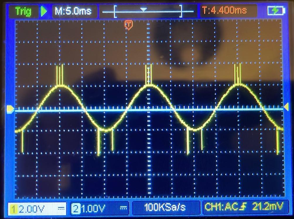
It is a 50 Hz sine wave with a peak of 1 V (2 Vpp) and in addition to that steep pulses (representing corona discharge) at both peaks of the half waves (approx. 1 Vp), leading to a total of approx. 4 V peak-to-peak. According to an oscilloscope reading, the rise time of each corona pulse is approx. 50 V/us (1V/20 ns) and the width is approximately 1 us each.

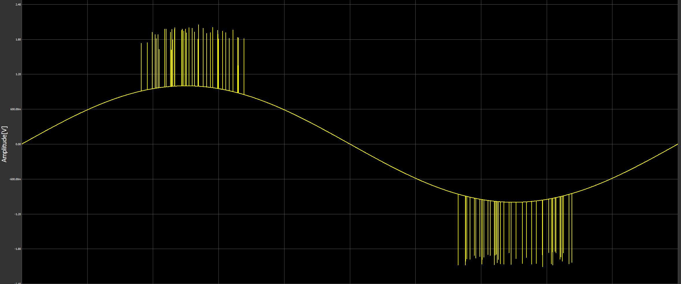
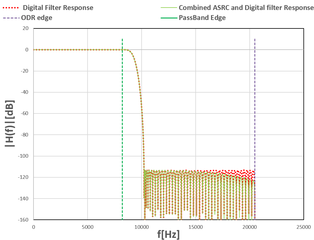
The ADC has a very steep analog and digital filter at around 9 kHz: enter image description here What I do not understand is that with this input at the ADC (yellow) my DSP behind the ADC tells me that my signal peaks are +- 4 V (8 Vpp) -> hence the Corona signal is not filtered out! Why is this? enter image description here

On the ADC signal I perform an FFT. When I add these corona pulses, I get a significant contribution to 150 Hz amplitude in the FFT output. When I have corona pulses in only one half wave, I get 100 Hz contribution.

At first I thought the real-life corona pulses may overdrive my front end concerning signal magnitudes (railing of input op-amp,) but from my test described above, I know that 4 Vpp is well within the output range of all op-amps (and input range of my ADC: 8 Vpp.)

Question:

Can it be that a too slow slew rate of one or multiple OP amps in my analog front end causes the modulation of a low frequency (150 Hz) signal (some kind of OP amp dynamic saturation due to the pulses?) If this is the case, what would help?

\$\endgroup\$
6
  • 1
    \$\begingroup\$ Why do you think a 9KHz low pass should remove those peaks? From what you have said they have strong signal components at much lower frequencies, so they should not be removed. \$\endgroup\$ Commented Jan 6 at 16:00
  • \$\begingroup\$ @user1850479: Yes the re-occurence of these peaks has a 150 Hz component but the pulses themselve a very high frequency. So I would think a low pass will filter these individual high frequency peaks/pulses and thereby their 150 Hz occurence. \$\endgroup\$
    – Maxim
    Commented Jan 6 at 16:18
  • 2
    \$\begingroup\$ It will filter the part of them that is above 9KHz, but everything else will remain. If you were thinking that the 150 Hz parts would be removed, no that's not what a 9khz low pass filter does. Have you tried varying the low pass filter cut off to see how low it needs to be to get the result you want? \$\endgroup\$ Commented Jan 6 at 16:27
  • \$\begingroup\$ A median filter could be more effective in removing short spikes. \$\endgroup\$
    – jpa
    Commented Jan 7 at 13:08
  • \$\begingroup\$ @jpa Where exactly? Digitally or at analog side. Do you have any references? I could only find information for digital filters (mostly for pictures etc.). Thanks! \$\endgroup\$
    – Maxim
    Commented Jan 7 at 13:54

4 Answers 4

8
\$\begingroup\$

This would be expected. Your Corona discharges are not random, they occur near the positive and negative peaks of the sine, and they always add to the amplitude. So, the Corona pulses have a 150 Hz component to them.

\$\endgroup\$
9
  • \$\begingroup\$ I would agree, but I though that these Corona spikes (due to their high-frequency nature) would be insivisible to my ADC (and subsequent FFT) due to the strong ADC filter (AD4134 is used). Hence, I suspected some kind of modulation of these peaks due to OP amp saturation or similar (what I explained above). \$\endgroup\$
    – Maxim
    Commented Jan 6 at 10:13
  • 1
    \$\begingroup\$ @Maxim The LP filter cut-off is 9kHz, but the corona pulses, as Mattman944 explained, have a strong 150Hz component, well within the filter's pass band. If those pulses were permanently present, and not occurring periodically at 150Hz, then their 150Hz component would disappear, and the filter would be very effective. \$\endgroup\$ Commented Jan 6 at 13:56
  • \$\begingroup\$ @SimonFitch: Thank you. Still I do not understand why these high frequency peaks are not filtered by the ADC low pass (I added the filter response and a new measurement above). Maybe I am not getting exactly how the ADC filter works/or does not work. \$\endgroup\$
    – Maxim
    Commented Jan 6 at 15:46
  • 1
    \$\begingroup\$ @Maxim - Even if you have a perfect 9 kHz low-pass filter, the high-frequency spikes have some low-frequency periodicity to them, so they have some low-frequency content. BobFlux explained it better than I did. \$\endgroup\$
    – Mattman944
    Commented Jan 6 at 16:55
  • \$\begingroup\$ @Maxim - You could do more research on Fourier transforms, Or, what I like to do, to really understand something, is to create artificial data sets (like BobFlux did) and run FFTs on them. If you have a working C compiler on your PC, that would be a good start. I use KISS FFT, you can download it for free. If I had used this C project more recently, I would run some examples myself. But, it will take me many hours to refresh my memory, and I don't have time right now. \$\endgroup\$
    – Mattman944
    Commented Jan 6 at 17:09
5
\$\begingroup\$

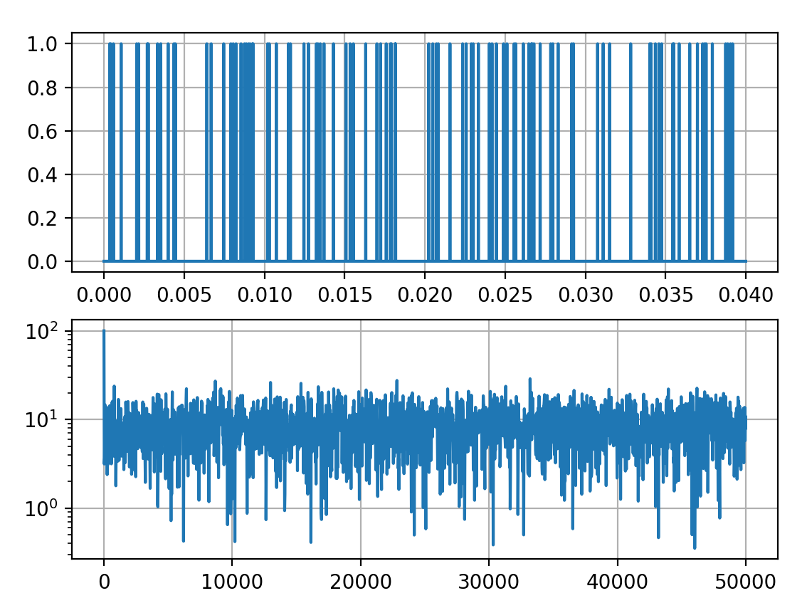
Assuming each pulse is fast enough to look like a Dirac pulse, its spectrum is a flat constant across all frequencies. Realistically, it won't go to "infinity Hertz" but you can expect a wideband spectrum.

Now imagine a train of pulses happening at random times. The spectrum of that is the sum of spectra of the individual pulses, taking into account the time when each pulse occurs.

In the frequency domain, a time delay is equivalent to multiplying the whole spectrum by \$ e^{j\omega t} \$.

So the spectrum of the above signal is the sum of \$ e^{j\omega t_n} \$ with \$ t_n \$ being the arrival time of each pulse, which is random.

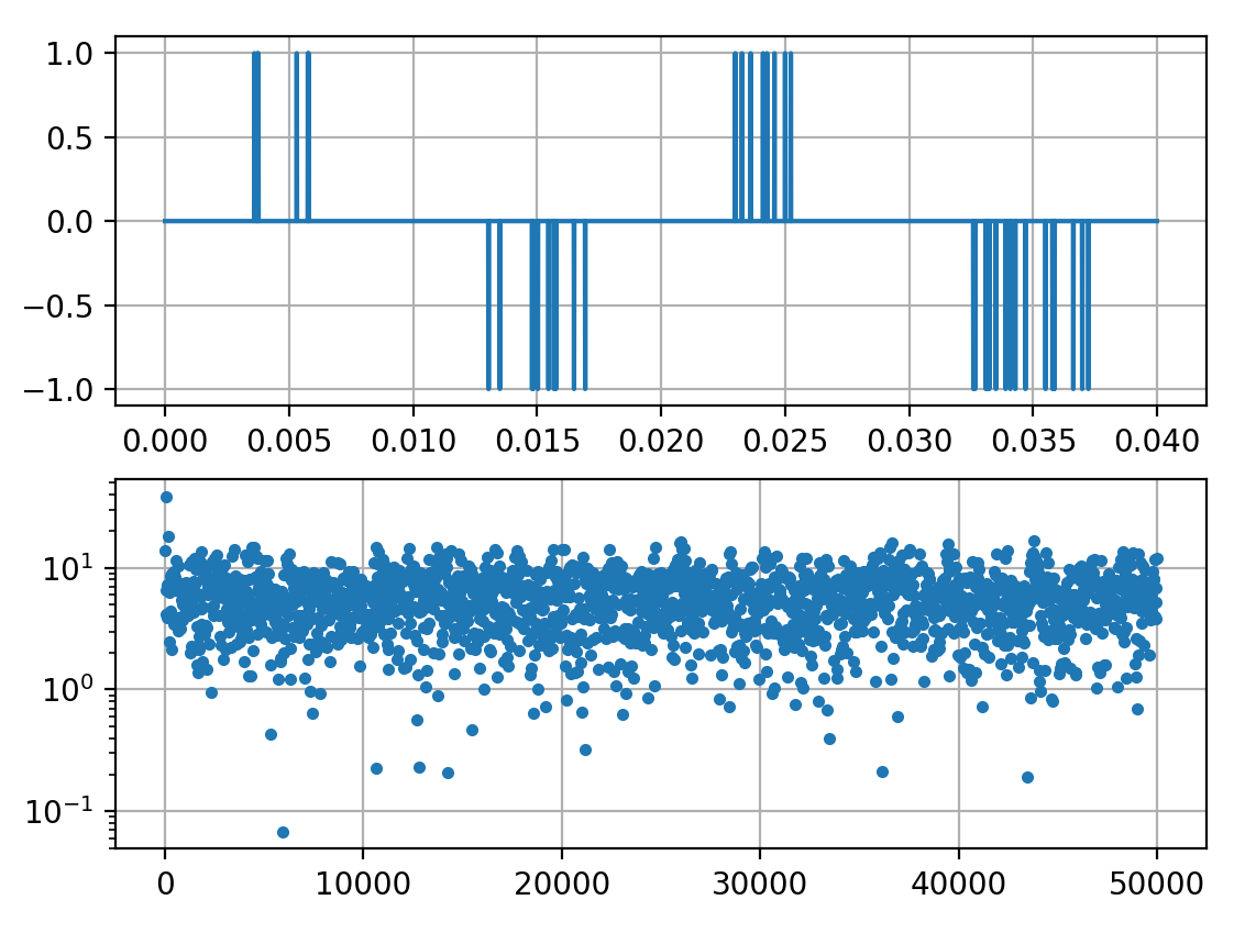
On average, this spectrum also has constant power across frequency. In the frequency domain, the sequence of random pulses above is indistinguishable from white noise. Signal on top, spectrum on the bottom:

enter image description here

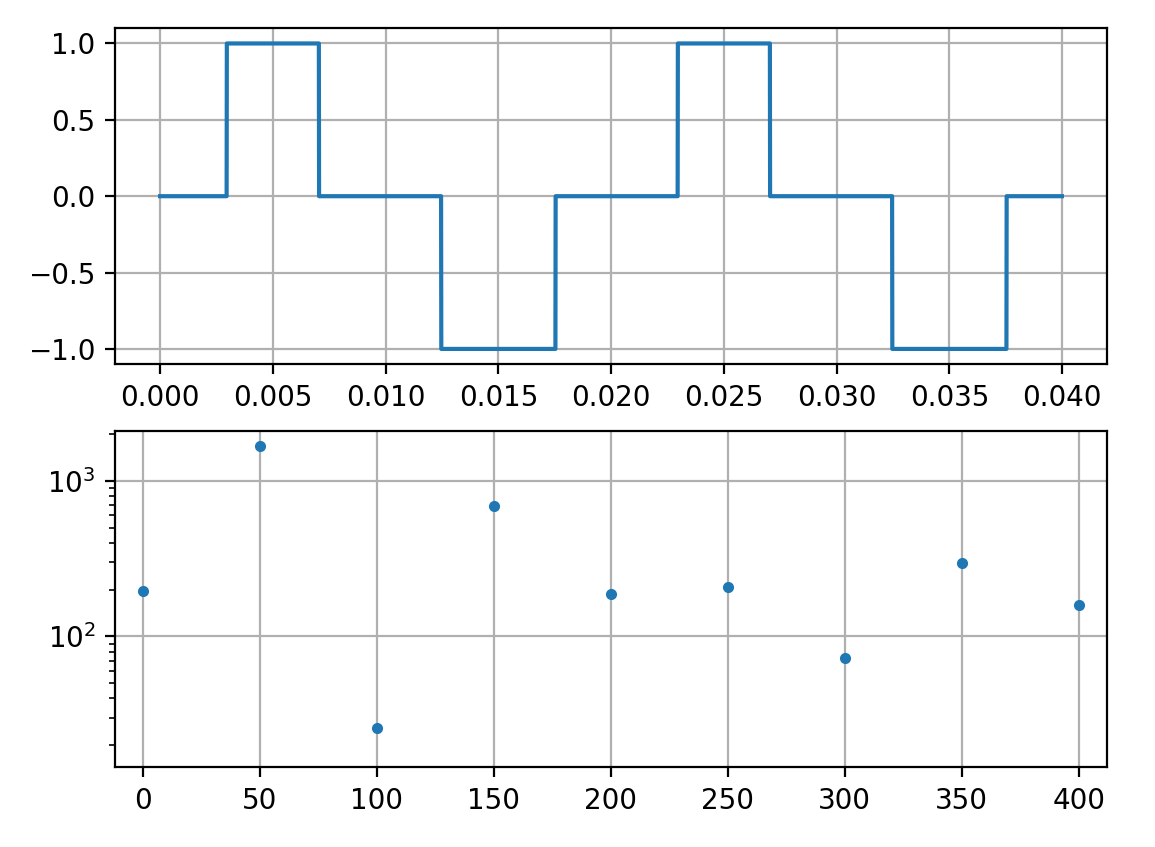
Now let's multiply this pulse train with the gating signal below:

enter image description here

This gating signal is 50Hz periodic, so it has harmonics of the 50Hz fundamental. If the two pulses are symmetric, it'll only be odd harmonics, but if they are not you'll get a mix of even and odd. This is what you're seeing here:

When I add these corona pulses, I get a significant contribution to 150 Hz amplitude in the FFT output. When I have corona pulses in only one half wave, I get 100 Hz contribution.

Now let's multiply the pulse train and the gating signal.

enter image description here

Time domain multiplication is frequency domain convolution, so the spectrum is the convolution of the pulse signal spectrum (white noise) and the gating signal.

And the result is... white noise.

The question you're not asking is: why aren't you getting energy at all the other frequencies, say between 100Hz and 150Hz?

If you're only doing a 1-period FFT then these frequencies are not in the result so it's expected, but if you're using more than 1 period you should be getting lots of noise in all the bins. It's absolutely normal, that's what your signal actually is.

Can it be that a too slow slew rate

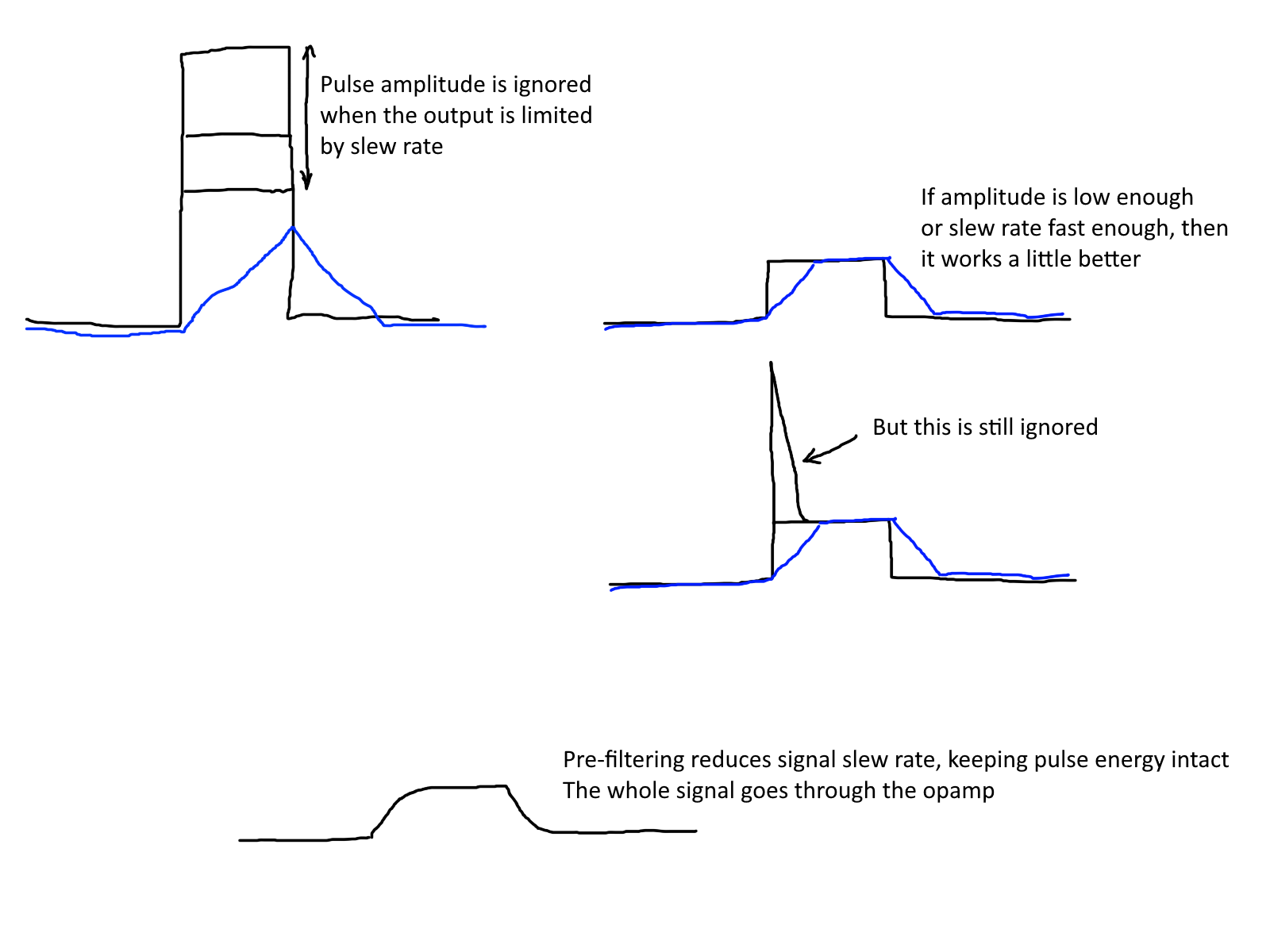
No, but if you want to measure the energy of these pulses, then the opamp must not slew limit. If it does, then it will miss a portion of the pulse:

enter image description here

Black is the input pulse. Blue is the output of the opamp, with severe slew limiting. In this case it is not possible to know what the amplitude of the pulse was, because the opamp never got there.

Low pass filtering averages the signal, it is linear, so the information you want to measure is preserved within the filter bandwidth. Slew rate limiting ignores the signal so whatever happens during slewing is simply lost information.

So you should definitely do enough filtering before your opamps to make sure they don't slew limit.

But that won't remove the 100Hz and 150Hz components, because these are actually your signal.

\$\endgroup\$
7
  • \$\begingroup\$ Thank you! That was educational. The full truth is that in reality I also see FFT components between 100 Hz and 200 Hz (or more) but usually peaking at approx. 150 Hz. The Corona signal above was constructed/reverse-engineered to see a peak in 150 Hz (as I do in reality) but tbh I do not know how the input looks in reality. However, I cannot wrap my head around, why the ADC does not filter out these high frequency peaks (I added its filter response above). I also added new measurements above. \$\endgroup\$
    – Maxim
    Commented Jan 6 at 15:34
  • \$\begingroup\$ To add on this: I am not interested in the energy of the peaks. Would it then be reasonable (as a kind of filter) to have a lower slew rate for the input buffer (I am only interested in signals up to 10 kHz -> slew rate of approx. 4 V / 25 us = 0.16 V/us). The Corona discharge of the peaks is above this threshold. \$\endgroup\$
    – Maxim
    Commented Jan 6 at 15:52
  • 1
    \$\begingroup\$ Can you post a plot of the digitized signal from the ADC? Most likely the peaks will be smoothed by the filter, as the high frequency components that make the waveforms sharp will be removed. But as the others said, the peaks have frequency components well inside your filter's passband, so these will not be removed. \$\endgroup\$
    – bobflux
    Commented Jan 6 at 16:06
  • 1
    \$\begingroup\$ Can you give info about what ADC chip you're using? Also if your analog signal chain includes analog filtering or not. \$\endgroup\$
    – bobflux
    Commented Jan 6 at 16:08
  • \$\begingroup\$ I use ADC AD4134. Before the Input Buffer there is a 1st order LP in my real measurements (not in the ones I posted, as, there, I inject the artificial signal directly into the Input Buffer). I will update my question with the digitized ADC output soon. I just need to fire up Logic Analyzer. \$\endgroup\$
    – Maxim
    Commented Jan 6 at 16:47
3
\$\begingroup\$

If your corona pulses were bipolar, that is added signals above and below the 50 Hz waveform, then you would not expect to see 150 Hz signals.

However, your corona pulses are only positive during the positive half cycle, and only negative during the negative half cycle. This only adds to the amplitude, and so looks like odd harmonic distortion of the fundamental 50 Hz waveform. It's the opposite of what happens to a mains waveform that gets clipped in voltage by all of the rectifier loads on it drawing current, which adds odd harmonics, principally the 3rd. As the additional amplitude is symmetrical, there are no even multiples of 50 Hz.

A similar thing occurs when you have corona pulses only on one half of the waveform. You now have an asymmetric pulsey waveform at a 50 Hz fundamental, which has all harmonics, even and odd.

It would be quite easy to see that the corona pulses have this energy at harmonics of 50 Hz by zeroing the amplitude of the 50 Hz sinewave, while leaving the pulses present. FFT, and you'll see the harmonic energy.

\$\endgroup\$
3
\$\begingroup\$

In addition to existing answers (bobflux's in particular), there is another effect that may be worth considering.

Many op-amps, and other semiconductor circuits, are susceptible to RF rectification effects.

About Bandwidth

It's not perfectly clear just how wideband your signals are -- for example, if you merely inspected them at a slow sweep rate (on the oscilloscope), you might get only one sample during a given peak, and considerable aliasing (most of the peaks missing, some runted, few resolved to full amplitude).

It's reasonable to suspect this, because gas discharge phenomena in general can be extremely fast. For example, ESD has a risetime under 1ns. It's quite possible the individual corona spikes are similarly fast (and far taller), and you're already seeing either a smoothed out, or aliased, mush of what's really there.

It's also possible you've ruled this out, having inspected the signal at high sample rate (with adequate scope bandwidth, and controlled-impedance probing technique, etc.); but given the data presented here, the above remains a possibility.

(On that note, the edit including the oscilloscope waveform was made while composing this answer. Notice the far lower density of peaks compared to the original screenshot. This seems to further confirm my above concern.)

Rectification

As for this, the general effect is, a semiconductor junction gets forward-biased (or avalanche too) during the peaks, causing signal clipping, but also an unexpected current flow, which is modulated by the sum of intended (here, the sine wave) and noise (the corona interference*) components. The current pushes against the baseline value of the signal, shifting it.

Thus, a mixing effect occurs, and harmonics and intermodulation products are generated. Which includes signal-frequency and DC components. Which can even be exaggerated, by knock-on effects like charge storage and reverse recovery.

*Well, maybe it's intended too, but point being it's a very random signal, and constitutes significant EMI and RFI if present in a real-world environment.

Besides direct mixing, nonlinear current flows can result, for example diode junctions charging the capacitance of internal gain nodes during the peaks, which are restored to normal levels only gradually by internal bias currents. An op-amp's input transistors (or elsewhere internally) can act like capacitor-input rectifiers, causing the internal nodes to follow the peak voltage of the signal. Thus, an incident RF envelope can manifest as an input bias voltage.

Op-amp slew rate can also be asymmetrical, so that when repetitive limiting occurs, the output (or internal gain node(s)) become biased off-center from the real mean voltage. Thus apparently reading an input offset voltage, when everything is actually working perfectly normally (i.e. even in the absence of rectification effects per se).

Mitigation

It can pay to apply even quite modest (e.g. single-pole) filtering, ahead of an analog front-end (AFE) circuit where these effects can occur.

The most susceptible op-amps tend to be bipolar types, where the input base-emitter junctions themselves act to rectify RF. Lower transconductance types, JFET, and especially MOSFET types, mitigate the effect at the direct input by biasing the junction to a higher voltage, or eliminating the junction entirely.

Many precision amps these days also boast onboard RFI filtering. More or less, an RC filter is integrated on-chip, effective perhaps from 100s of MHz, to well into the GHz where effective on-board filtering would even be a challenge.

Fast enough amps, of course, can also handle high slew rates without limiting or rectification.

The most general (and perhaps important) take-away, is this:

Use only what bandwidth you require.

Limit bandwidth early, and as often as necessary to maintain immunity, noise level, etc. (Mostly, internal bandwidth can be left un-limited, as there are fewer extenuating effects; but there may be special cases where you need additional immunity to external fields (onboard filtering cheaper than shields?), or to prevent device noise from mixing (and accumulating) with the signal.) If you need to resolve the spikes, you must have at least enough bandwidth to resolve the pulse width, or depending on exactly how much detail you want to resolve them to, the risetime or further details as well. How this bandwidth is arranged, doesn't matter -- you might well for example split it into a low-pass path for the mains-frequency stuff, and a band-pass path for the spikes.
\$\endgroup\$
5
  • \$\begingroup\$ Thank you very much. I am not interested in the spikes and would want to remove them completely if I could (my Signal Range of interest is 0…9 kHz). I already have a 1st order low pass before my first opamp in the real set up (not in the presented measurements above, where I inject directly into the input buffer) but this seems to not help (enough). Would it help/is it proper practice to also put a low pass after each of the 3 op amps as well? The ADC (AD4134) datasheet at least states that a LP at its entrance is not required due to its inherent Filter. \$\endgroup\$
    – Maxim
    Commented Jan 6 at 17:05
  • \$\begingroup\$ That sounds like a good start at least, but I can think of other possibilities that apply that aren't mentioned in such a description. You'd have to show your full input chain to be sure. Perhaps ask a new question to review that with respect to this issue? \$\endgroup\$ Commented Jan 6 at 19:40
  • \$\begingroup\$ I could do that for sure and would be very interested in the alternatives but basically it is an RC divider and a subsequent RC lowpass and then the 3 op Amps mentioned in my question directly connected in series (and at the end the adc). If you still think a new question makes sense, let me know how to tag you on this one then :) \$\endgroup\$
    – Maxim
    Commented Jan 6 at 20:45
  • \$\begingroup\$ And no ESD diodes or anything, and nothing obviously funny about the source? That's probably fine then, down to RC time constant of course. \$\endgroup\$ Commented Jan 7 at 3:32
  • \$\begingroup\$ No ESD diodes. I mean the source is an electric field coupled via an high impedance antenna (RC divider). The Corona originate/come from from the electric field. Then a simple RC low pass (connected between at the midpoint of the RC divider) and the mentioned 3 op amps. \$\endgroup\$
    – Maxim
    Commented Jan 7 at 10:07

Your Answer

By clicking “Post Your Answer”, you agree to our terms of service and acknowledge you have read our privacy policy.

Not the answer you're looking for? Browse other questions tagged or ask your own question.