What I needed to know back then
Back then I didn't know there is something called microcontroller.
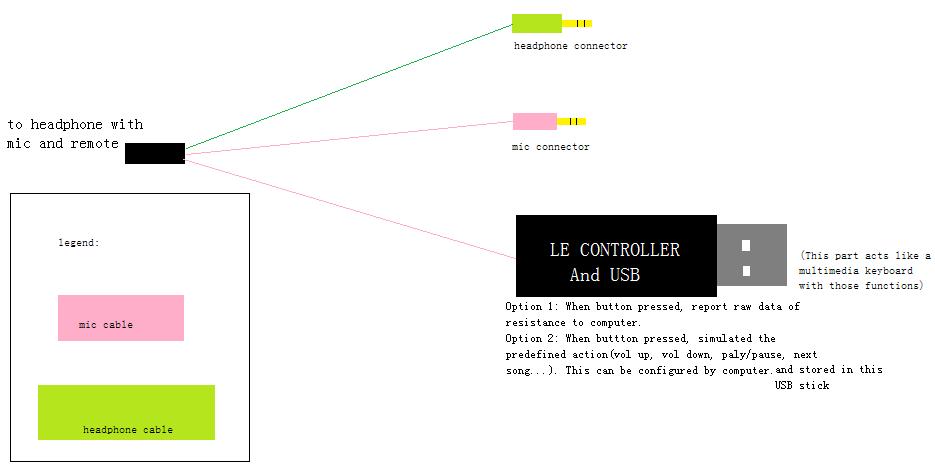
What I need is a microcontroller with integrated ADC and USB interface.
I also didn't know about how capacitors appear like a short circuit for AC signal and open circuit for DC signal, how transistors work as an amplifier, that there is an amplifier in electret microphones, and most of the line control section microphones are electret.
What's in a headset line control
Buttons
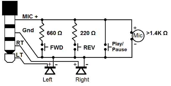
The buttons in the microphone and media control section are connected this way according to this answer.

(The FWD and REV should probably be VolUp and VolDown)
Electret microphone capsule
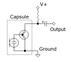
The electret microphone capsule usually contains something like this:
 (from this answer)
I'm not good with amplifier and AC signal stuff, so correct me in the comments if this circuit is wrong or I'm wrong.
Trying to explain how this works:
The FET configuration looks like a common source amplifier. According to the answer linked beside the picture above, the electret mic diaphragm itself is permanently charged to a DC voltage that puts the FET in the saturation region (with an appropriate drain resistance)(so it can be used as an amplifier). The vibration of the diaphragm will create a small AC voltage around the DC bias. This AC signal will be amplified by the FET, and the amplified signal will also be present around the DC voltage level on the drain of the FET. The AC signal can be coupled to another DC level through the output capacitor. The computer/mobile phone can then further process that AC signal.
Not sure what it means for the mic to be >1.4kOhm. Probably the DC voltage on the FET drain is equivalent to the voltage generated from a resistor divider with the drain resistor and a resistor greater than 1.4kOhm.
Putting it together
The basic idea is to use the microcontroller ADC to read the DC voltage on the mic line, so the resistance (or "resistance" for the mic capsule) between the mic pin and ground can be known. Then, the USB interface on the microcontroller can be configured as an HID keyboard. Depending on the calculated resistance and how the buttons are pressed (double click for forward, single click for play/pause etc), the microcontroller can choose to do nothing (when no button is pressed) or send the corresponding media button keycode through USB.
The other thing to consider is how to acquire the resistance between mic and ground pin. Since most ADCs in microcontroller uses a sample-and-hold circuit which contains a capacitor to ground or a fixed voltage level, a voltage buffer might need be used to avoid attenuating the microphone audio signal.
In addition, the voltage on the mic pin is dependent on the supply voltage and resistor in the computer's microphone input. If those are standard, I can simply connect the mic wire to the ADC's voltage buffer input. However, from the comments in this answer, it looks like the voltage and resistor could be anything. Thus, it would be kind of difficult to know the voltage range for each button. So it might be better to provide a supply voltage and biasing resistor from the microcontroller side, then couple the microphone signal through the capacitor to the computer's microphone input. A resistor (probably around 1.4k to 4.7k, depending on the typical biasing/drain resistor in computers) should also be added to shift the DC operating point down, so the signal doesn't get cut off in the computer's ADC input.


