0
\$\begingroup\$

I'm using the USART on an STM32F4 series MCU. I'm wondering how the receiver detects the start bit when oversampling by 8 is set.

The reference manual says the start bit detection sequence is the same when oversampling by 16 or by 8. The start.bit is confirmed when the 3 sampled bits are at zero (first sampling on the 3rd, 5th, 7th bits finds the 3 bits at 0 and second sampling on the 8th, 9th, 10th bits also finds the 3 bits are at 0).

However, the sampling rate is 8 times the baud rate clock, when oversampling by 8 is set, the receiver engine samples a one-bit period 8 times. That means it takes 8 samples to understand that bit.

It makes me confused there are only 8 sampling points, but the length of the start bit detection sequence is greater than 8 (the 3rd, 5th, 7th and the 8th, 9th, 10th sampling points). I have no idea how to explain this part of the manual.

additional: I have added a simple drawing of oversampling 16. From hardware perspective,the one-bit periond of data sampled is the same as time that the RX_Counter which is driven by baud clock counting to 16. It can locate the sample1 & sample2 which are required sampling ponits using the counter easily. However, if oversampling 8 is set, the counter only can count to 8.If both oversampling methods use the same start bit detection sequence, the sample1 & sample2 can not be located.

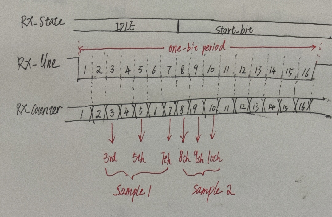
enter image description here

\$\endgroup\$
3
  • \$\begingroup\$ This may not be very clear unless the question has a simple drawing to clarify the points of transition from 16 samples/bit to 8 samples/bit. This could be hardware specific. \$\endgroup\$
    – Sparky256
    Commented Feb 1 at 6:38
  • \$\begingroup\$ @Sparky256 Exactly, the datasheet drawings in the specific microcontroller series this question is about do not show such a point of transition, so it is hardware specific. \$\endgroup\$
    – Justme
    Commented Feb 1 at 6:49
  • \$\begingroup\$ That image is simply a hand-drawn copy of a diagram in reference manual. And my answer already covers the case - When you set oversampling to 8, the start bit does not need to use same oversampling ratio as the data bits. \$\endgroup\$
    – Justme
    Commented Feb 1 at 8:59

2 Answers 2

1
\$\begingroup\$

The relationship between oversampling by 8 or 16 may only relate to the data bit reception, not the start bit detection.

Using the 8x oversampling requires the OVER8 bit to be set, but also requires the fractional baud rate setting to use one fractional bit less. So clearly it does not directly switch everything to be 8x, or use 8 clocks per bit rate, instead of using 16 clocks per bit rate.

Internally, it is possible that during start bit detection, it still runs at 16x oversampling to detect the start bit edge more accurately, and then when it has been synchronized, the data bits are clocked every 8 sampling clocks to achieve higher baud rate instead of clocked every 16 sampling clocks. In other words, the start bit detection may still run at double speed compared to the data reception.

This might be in contrast to an Atmel AVR, which by setting the U2X bit to change from 16x to 8x oversampling, it switches everything to be sampled at 8x so also the start bit edge is detected less accurately at resolution of 8x times the bit rate. The baud rate register directly sets the oversampling clock divider, and everything is then set to use 16 or 8 clocks depending on which oversampling ratio user selected.

\$\endgroup\$
1
  • \$\begingroup\$ Thanks for your answer. I have provided additional supplement. \$\endgroup\$
    – chan peng
    Commented Feb 1 at 7:52
0
\$\begingroup\$

Remember that in asynchronous serial data, 10 bits are sent to the receiver. One start bit followed by a byte of data (8 bits), possibly followed by a stop bit.

Detection of all 9 or 10 bits enables the receiver to "frame" the byte of data and move it to the data buffer (with the start/stop bits stripped out). This may also set the RD flag in some MPUs that only have a one byte buffer.

I could be making some incorrect assumptions about how this hardware frames a byte of data using multiple sample rates. Over the decades many schemes have been used, usually getting better with time.

Higher sample rates early on can be used to capture the starting bit and help the PLL better lock onto the bit rate, so further sampling can be at fewer samples per bit.

Encrypted data would be treated the same way, as it is outside of the basic process of transferring single bytes of data.

NOTE: This does not include the added complexities of ethernet or USB data packets which are outside the scope of the question.

\$\endgroup\$
4
  • \$\begingroup\$ I think you misunderstood the question. This answers something else instead of what was asked. \$\endgroup\$
    – Justme
    Commented Feb 1 at 5:36
  • \$\begingroup\$ @Justme I understand oversampling bits and bytes, to capture a bit or a byte. The OP maybe confused about this. \$\endgroup\$
    – Sparky256
    Commented Feb 1 at 6:21
  • \$\begingroup\$ The question is clear to me. Why in this certain MCU, the start bit detection sequence appears to use 16x oversampling even if you select 8x oversampling to get higher bit rates. I'd like to know what you think is being asked, to understand how your answer relates to the question. \$\endgroup\$
    – Justme
    Commented Feb 1 at 6:27
  • \$\begingroup\$ Thanks for your answer. I have provided additional supplement. \$\endgroup\$
    – chan peng
    Commented Feb 1 at 7:52

Your Answer

By clicking “Post Your Answer”, you agree to our terms of service and acknowledge you have read our privacy policy.

Not the answer you're looking for? Browse other questions tagged or ask your own question.