0
\$\begingroup\$

I have a 12 volt dc to 120 volt ac inverter built into my custom van. I've been curious if it produces a modified or pure sine wave because I have a need to occasionally plug a ebike battery charger into its outlet and am concerned that a modified sine wave may damage the charger's internal circuitry, not to mention the ebike's battery.

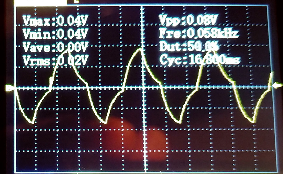
I determined that, to obtain the sine wave I can use a amp clamp which converts current into voltage and this amp clamp will be connected to a FNIRSI DSO152 digital mini scope and obtain the clamp reading by plugging a AC line splitter into the inverter's outlet and then plug a 30 watt incandescent bulb into the line splitter so that the amp clamp can obtain a reading by clamping over the line splitter at the 10X section. I figured that the amp wave should be identical to the voltage wave and safer for me to obtain that pattern with the equipment I have.

The settings on the scope was 20 milli volts, 5 milli seconds, ac current.

The photo here displays the result. It appears to be a reasonable approximation of a pure sine wave but not a pure sine wave. Then again, it isn't a standard modified sine wave either. Note, also, that I connected this setup to mains current and three other known pure sine inverters all of which produced an obvious pure sine wave so I feel that my method is valid.

Any thoughts?

enter image description here

\$\endgroup\$
4
  • \$\begingroup\$ HLM - I have merged your reposted question with this original question you asked. I have also undeleted & reopened this one, now that you added the main piece of requested information (the scope settings). Please note that doing a "delete & repost" of a question is not allowed, especially since you did it to bypass this question being closed, while it was waiting for review. TY || Note: You were previously also asked to provide a schematic of how you connected the various pieces of measurement equipment together. Adding a photo of the test setup may also help people to understand it. \$\endgroup\$
    – SamGibson
    Commented Feb 21 at 1:32
  • \$\begingroup\$ Anything else to state about the setup, like using a 100:1 probe? \$\endgroup\$
    – greybeard
    Commented Feb 21 at 6:32
  • \$\begingroup\$ I didn't use a 100:1 probe but, rather, a amp clamp set on the 40 amp scale for sensitivity and for the fact that the current I was running was a 30 watt incandescent bulb (low amperage). \$\endgroup\$
    – HLM
    Commented Feb 22 at 1:29
  • \$\begingroup\$ Note that I obtained the exact same waveform on a known modified wave inverter which elicited the exact same wave. So, at least I know that the inverter is definately a modified inverter. Still, in examining other modified inverter waveforms online I've not yet seen one like the one shown here. \$\endgroup\$
    – HLM
    Commented Feb 22 at 1:31

2 Answers 2

1
\$\begingroup\$

It looks like just L output filter where 5ms is positive supplying cycle, 5ms just discharging L through freewheeling diode, 5ms negative supplying and another 5ms discharge L via freewheeling diode.

So most probably there must be a big bulky inductor on output working without pwm.

\$\endgroup\$
3
  • \$\begingroup\$ Michal Podmanicky. Being that I'm not an engineer, etc. Is it fair to say that your reply here, in layman's terms is as follows: It seems like there's a simple setup involving an output filter. For 5 milliseconds, power is sent out in a positive cycle. Then, for the next 5 milliseconds, the energy stored in the system is released through a freewheeling diode. After that, for another 5 milliseconds, power is sent out in a negative cycle. Finally, in the last 5 milliseconds, any remaining energy is discharged through the freewheeling diode again. This process repeats in a cycle. \$\endgroup\$
    – HLM
    Commented Feb 22 at 1:39
  • \$\begingroup\$ To continue from Mr. Podmanicky: So, most probably there must be a big bulky inductor outputting without a pulse width modulator? \$\endgroup\$
    – HLM
    Commented Feb 22 at 1:39
  • \$\begingroup\$ Mr. Podmanicky, so are you saying that you are describing how these inverters with this waveform attempts to develop a sine wave and, therefore, this is a modified sine wave? If so, great, but is this waveform good enough to work for sensitive electronics (a CPAP machine, a laptop, etc.)? \$\endgroup\$
    – HLM
    Commented Feb 22 at 1:42
0
\$\begingroup\$

The shape certainly does not look like a pure sine, but then again no source will give an absolutely pure sine and this might be good enough. It also seems from your question that you measured current, not votage (you mention a "clamp"). And the current shape might differ from that of the voltage, if the load is not a linear resistor. If the 30 Watt light bulb was an old-fashioned incandescent bulb then this is no problem, of course.

\$\endgroup\$

Your Answer

By clicking “Post Your Answer”, you agree to our terms of service and acknowledge you have read our privacy policy.

Not the answer you're looking for? Browse other questions tagged or ask your own question.