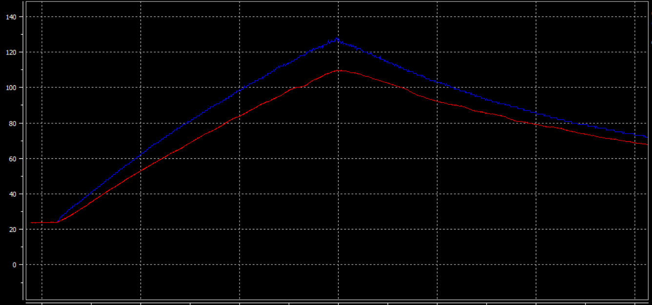
First, as MCG pointed out in their comment, make sure that the sensors are calibrated and verified.
I attached a thermocouple type K to the junction of the shunt using epoxy
I do a similar thing when I want to measure, for example, surface temperatures of some critical components on a PCB. I use double-component epoxy (namely DP100) to secure the T/C in place.
the potential causes of this result.
One thing I noticed with this method (using epoxy with T/Cs) is that if somehow the T/C is not in good contact, or in other words if there's any epoxy between the test surface and the T/C the results differ by a substantial amount. That's because the poor thermal conductivity of the epoxy (less than 0.02 W/m-K for DP100 in my case). A recent example: I measured the solder-point temperatures from the drains of two synchronous rectifier MOSFETs in DFN5x6-package placed side-by-side, one showed 98°C whilst the other did 105°C. After re-attaching the sensors "properly" the difference reduced to ~3°C.
One other thing is the convection. If you use a ball-type T/C like this one and attach it to a surface you need to isolate the rest of the sensor because a very small surface of the T/C is in contact with the target surface so the remaining may get "cooled down" by the air convection. The isolation is normally done by the epoxy but it still worth considering.

If it's possible for the NTC's temperature to be higher, why is that?
As for the NTC, the only thing comes to my mind is the self heating due to the biasing. You use an NTC as part of a voltage divider or you drive it with a constant current. Either way, the current flowing through it will cause a power dissipation which then results in self heating. You need to check the datasheet for the maximum allowed bias currents to bring the minimal self heating.


