5
\$\begingroup\$

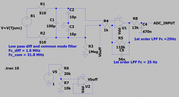
My application requires 11 thermocouples to be sampled and logged. Below is the circuit diagram, containing a differential and common mode filter, non-inverting amplifier (gain 111) and a second order LPF. The Vbuff voltage is a buffer voltage to ensure the output of the non-inverting amplifier is always positive, as the thermocouple needs to be able to read from -40C to 1000C. This Vbuff is shared between all 11 thermocouple circuits.

Circuit diagram Circuit diagram

  • U1 is a LMV844QMA/NOPB
  • U2 is a TSX7191IYLT
  • Temp sense IC is a TMP236AQDBZTQ1

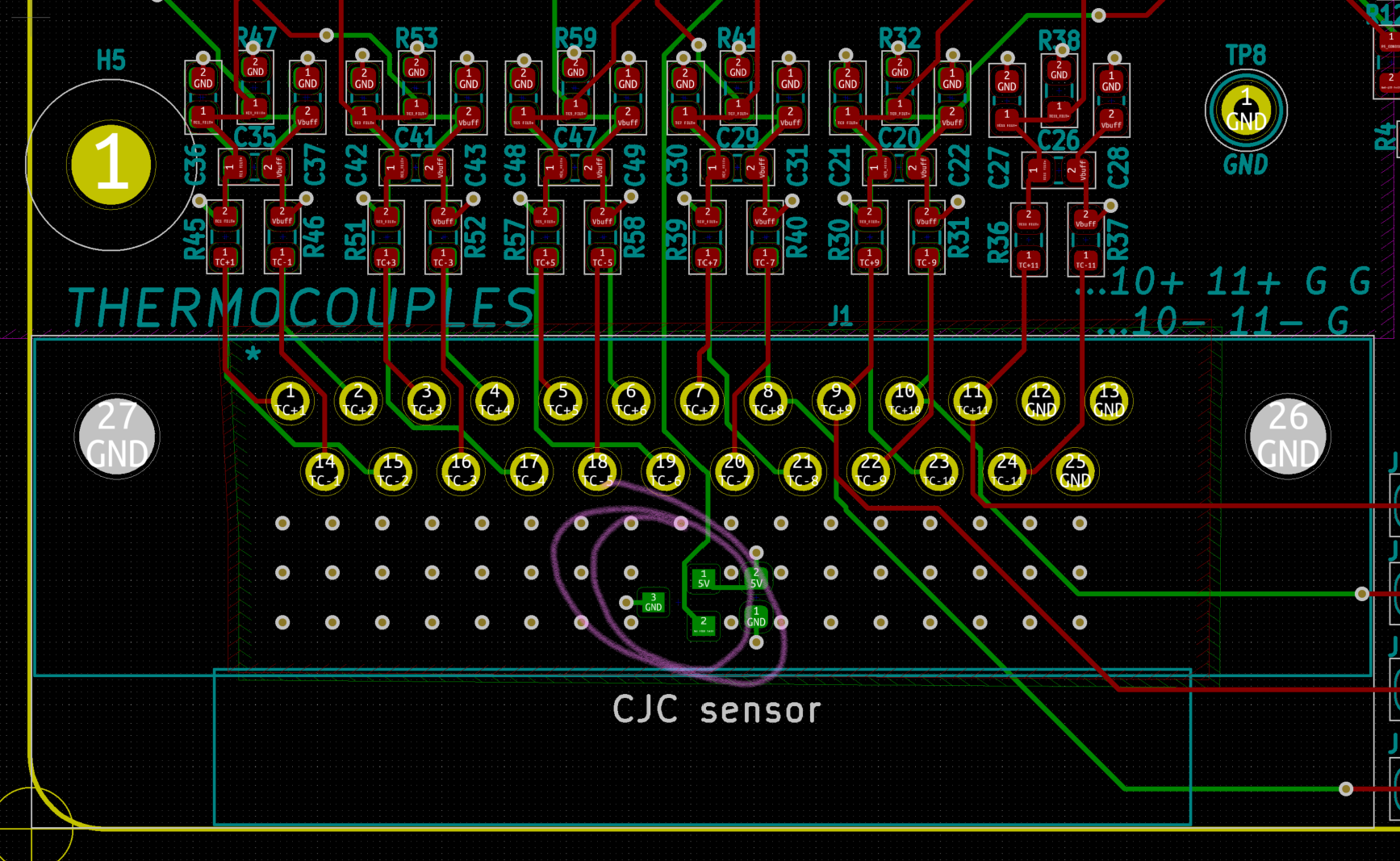
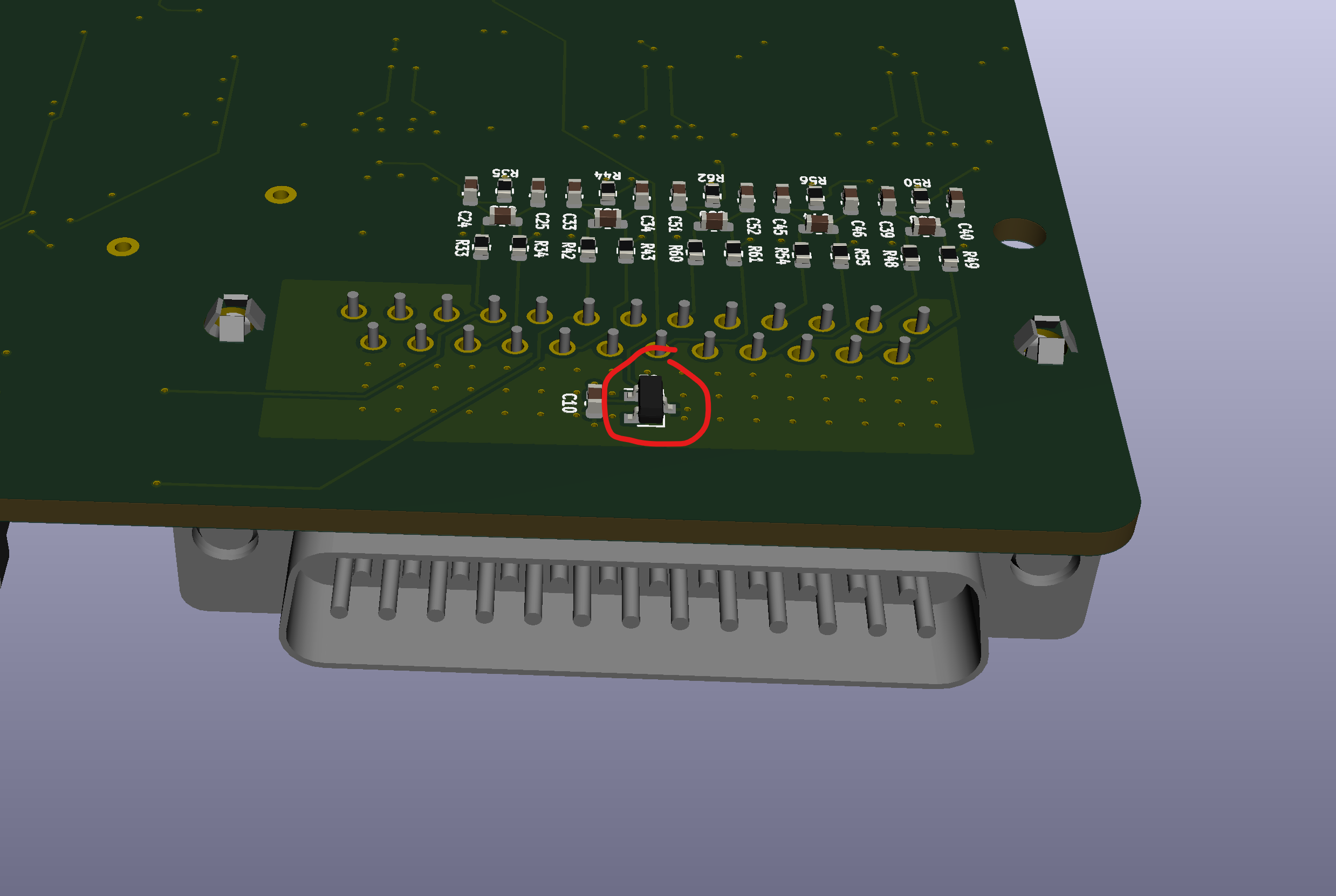
The location of the CJC temp sensing IC is directly below the thermocouple connector plug as shown in the images below. It is stitched to the ground plane for more thermal mass. At the moment the cables to the thermocouple are around 15-20cm.

CJC location 2D CJC location 3D CJC location

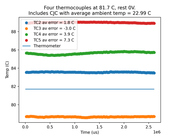
When holding four thermocouples in a hot water bath (I only have 4 on hand at the moment) I expect them to all read similar temperatures but the below plot shows they vary to each other by over 10 C. They also do not match the expected temperature well, as read by a thermometer. This plot includes cold junction compensation using a temperature sensing IC.

Hot water test

I have also tested them using a high-resolution power supply to simulate the thermocouple voltage. This showed similar discrepancies across the full input range, both between the thermocouple channels and to the expected value. The expected value in the below plot is the straight line, all other curves are the 11 thermocouples simulated using a power supply.

Power supply input for all 11 channels vs expected value Power supply input
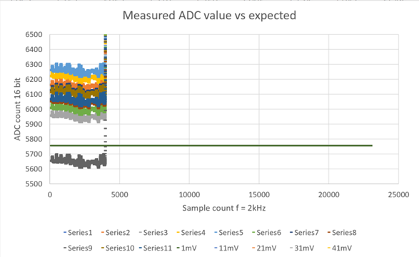
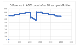
When calculating the difference between the highest and lowest channels it can be seen to approximate a linear slope with an offset component. The linear slope makes sense and would be due to tolerances on the resistors, which are all 1%. This was confirmed by swapping the resistors between the channels and the slope changed sign, as seen below.

Difference between highest and lowest channels Difference between highest and lowest channels
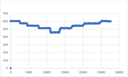
Difference between highest and lowest channels after swapping resistors

Difference between highest and lowest channels after swapping resistors

However, I am unsure what creates the offset, as this is the larger component of error. I understand that thermocouples can only achieve around +-2.5 C accuracy but I don't know where my larger errors between channels and compared to the expected value is coming from. Especially when simulating them using a power supply which means the errors are caused by my circuit, not the thermocouple itself. I am aiming for around 2-3 C of error between each thermocouple channel to the expected value.

Does anyone have any ideas for other things I could test to figure this out? I have plenty of other data and tests if you need any extra information. Any help would be greatly appreciated!

\$\endgroup\$
3
  • \$\begingroup\$ Where is your reference junction? And how do you measure / control its temperature? Or what is the part number of your compensation IC? \$\endgroup\$
    – D Duck
    Commented Jun 13, 2022 at 21:09
  • \$\begingroup\$ Added that information @DDuck \$\endgroup\$
    – AngusE
    Commented Jun 13, 2022 at 22:27
  • \$\begingroup\$ And that too @rdtsc \$\endgroup\$
    – AngusE
    Commented Jun 13, 2022 at 22:27

2 Answers 2

8
\$\begingroup\$

At more-or-less room temperatures, the voltage coefficient of a K-type thermocouple is about 40 uV/deg C. The LMV844 input offset voltage is typically +/- 50 uV, but is worst-case +/- 500 uV. So your potential offset range is about 25 degrees C.

\$\endgroup\$
1
  • \$\begingroup\$ As a hack (for this revision board), you might be able to tack in "adjustment" resistors/trimpots. Of course, those will introduce additional non-linearities; so while it might be possible to align them all at one temperature, they will diverge from there at slightly different rates... at best. \$\endgroup\$
    – rdtsc
    Commented Jun 14, 2022 at 11:55
3
\$\begingroup\$

The junction of the DSUB and connector will also act as a thermocouple, anytime you have two dissimilar metals, you get a thermocouple junction usually in the uV range. That is why thermocouples have special connectors, to match the junctions.

One way to overcome this is to fix the temperature of the electronics, and run a heater above ambient (at least 5C or above the room noise, so a 25C room would be 30C or 35C).

The other way is to use a specific thermocouple connector.

You could also find out how much the DSUB contributes by putting a block of metal around the DSUB and raising the temperature of the block to a controlled value (make sure it's insulated from ambient) and see how much that affects the thermocouple values. You can also ground the two connectors of the DSUB and also get an idea of what the error contribution is (but if you ground it you are introducing additional thermocouple effects

\$\endgroup\$
1
  • \$\begingroup\$ That's what the CJC sensor is for. It's not exactly on the connector, but it's pretty close by. All thermocouples should have a very similar cold junction offset, anyway, because they are attached to the same connector, which they clearly do not in the asker's experiment. \$\endgroup\$ Commented Jun 14, 2022 at 8:42

Your Answer

By clicking “Post Your Answer”, you agree to our terms of service and acknowledge you have read our privacy policy.

Not the answer you're looking for? Browse other questions tagged or ask your own question.