0
\$\begingroup\$

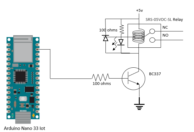
I'm currently using an Arduino Nano 33 IoT and would be powering 18 transistors - one digital pin to 1 transistor and with the use of the SDA and SCL pin to connect to 3 other I2C devices. I have run into an issue where my Nano 33 IoT will just switch off upon connecting the USB to my laptop. I suspect a power supply issue.

Is there any way I can power my Arduino to get it to output more current? I researched about the Vin pin when it can take in 7 to 21V external power supply but it seems there is a voltage regulator to regulate it back to 5V, so what is the point of using the Vin?

The 5V supplying the relay comes from the Vusb Pin of the Arduino

enter image description here

\$\endgroup\$
19
  • \$\begingroup\$ How did you connect to the transistor? It is more likely that you made an error in the connections that not being able to power 18 transistors. Unless you also power heavy loads from the USB supply. The point of VIN is to power the circuit standalone without USB with external supply that can be larger than 5V and still be able to make the 5V required by chips onboard. So show a diagram what you connected, where, and how. Including resistors if any. And the transistor type. \$\endgroup\$
    – Justme
    Commented Mar 6 at 12:39
  • \$\begingroup\$ @Justme Hi, thanks for the reply! Apologies, I shall try to get a diagram up, but the diagram is really complicated due to the amount of components I have. Do take a look and I'll be happy to clarify! I have added the diagram! \$\endgroup\$ Commented Mar 6 at 12:45
  • \$\begingroup\$ If you've got many channels with the same output circuit then just detail one of them, put a dotted outline around it and just show the outline for the other outputs. Oooh, too late. We've got the whole thing! Thanks. \$\endgroup\$
    – Transistor
    Commented Mar 6 at 12:48
  • \$\begingroup\$ We'll need a higher resolution image, I think. \$\endgroup\$
    – Transistor
    Commented Mar 6 at 12:50
  • 1
    \$\begingroup\$ @ArduinoRookie You left out which components those are. The resistor value in ohms, transistor model, and relay model. And the fact that you are powring 18 relays, not 18 transistors. And likely the relays can damage the transistors and Arduino since you left out a snubber diode from the coil. \$\endgroup\$
    – Justme
    Commented Mar 6 at 13:02

1 Answer 1

1
\$\begingroup\$

The 100 ohm base resistor is too small and allows too much current out from MCU IO pin. IO pins are rated for 7mA max and with 100 ohm resistor there could be more than double that. About 1mA would be enough.

Also you can't simultaneously power 18 relays that take 70mA each. Unless you enumerate with USB requesting the amount of current you need and get a permission to continue drawing that current. You can draw max 100mA without asking. 18 relays alone takes 1.3A which is absolute over the safe limit you can assume to draw, either from USB or through Arduino onboard 5V regulator.

\$\endgroup\$
3
  • \$\begingroup\$ Hello, thanks for the answer! ohh i see, in the current situation, would it be possible by powering up the arduino via the Vin pin and get a higher current output from the external supply? \$\endgroup\$ Commented Mar 6 at 15:45
  • \$\begingroup\$ @ArduinoRookie Maybe but the relays still consume a lot of 5V so why bother feeding the external 5V through the VIn anyway but directly to the relays. \$\endgroup\$
    – Justme
    Commented Mar 6 at 16:10
  • \$\begingroup\$ Ah i was thinking of powering the relays with a higher voltage supply and just supplying the arduino through Vin pin for higher current output to control the relays. \$\endgroup\$ Commented Mar 6 at 16:15

Not the answer you're looking for? Browse other questions tagged or ask your own question.