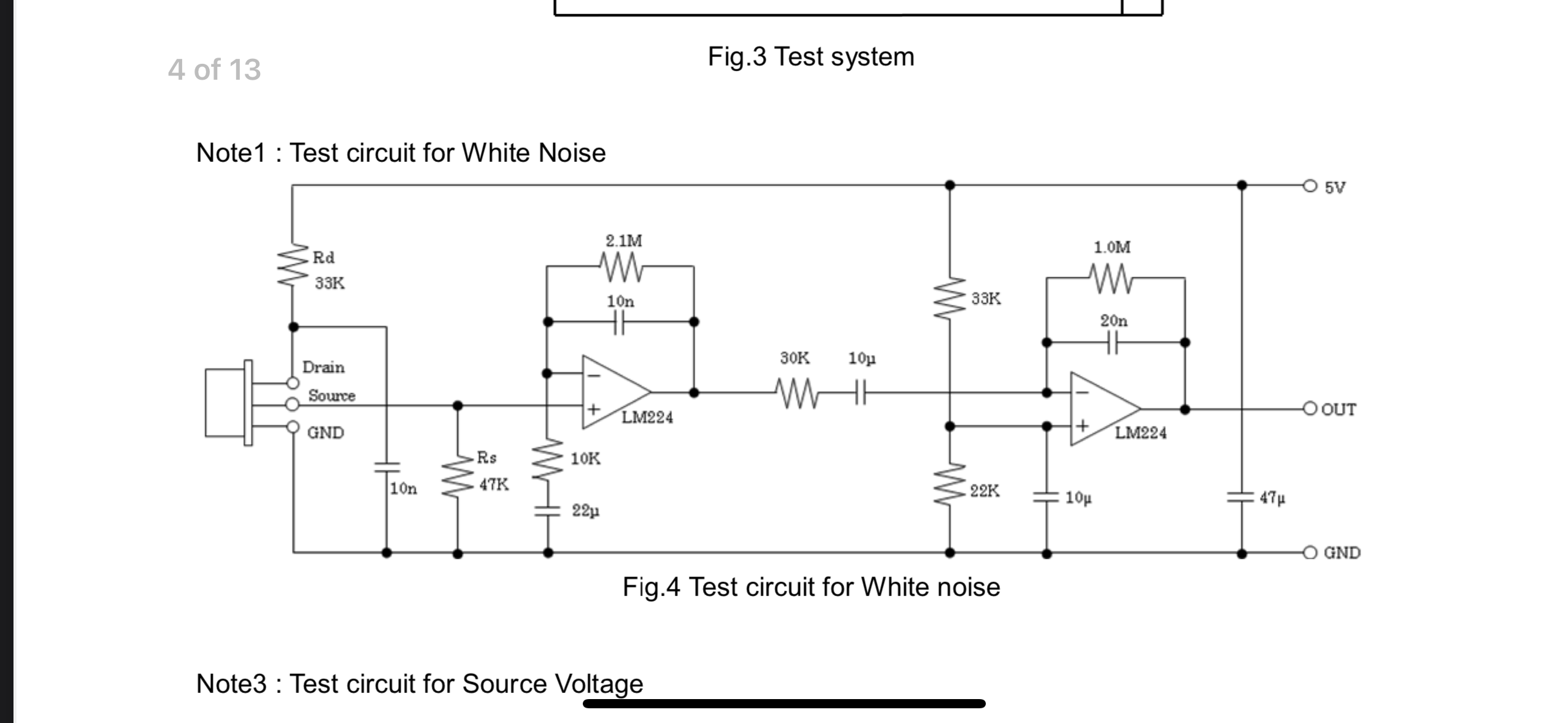
I have this PIR sensor circuit, can someone explain what each of the capacitors do in the circuit?
\$\begingroup\$
\$\endgroup\$
3
-
1\$\begingroup\$ At a guess, from left to right: 1st 10n shunts high frequency noise around infra-red detector, 22u reduces amplification of really slowly-changing signals (less sure here), 2nd 10n prevents high frequency noise being amplified, 1st 10u removes any DC component (decoupling), 2nd 10u shunts power supply noise away from the op amp input, 20n prevents high frequency noise being amplified, 47u smooths the 5V power supply. i.e. 22u ensures some reasonable change in the signal before amplifying (e.g. due to movement in the environment) and the other shunt capacitors eliminate unwanted noise. \$\endgroup\$– TonyCommented Mar 7 at 10:15
-
\$\begingroup\$ @Tony - Hi, Thanks for trying to help, but answering in a comment, as you did above, is not an allowed use of comments - see here & here. Therefore please consider moving that into an actual answer. (If you don't want to write it as an answer as you are too unsure, no-one is forcing you to do that - however please don't post answers, even guesses, as comments). \$\endgroup\$– SamGibson ♦Commented Mar 7 at 19:26
-
\$\begingroup\$ @user355274 - Hi again, To comply with the site rule on referencing, please edit the question & add the name and link of the PDF / video / webpage etc. which was the source of that schematic. (Or, if you copied it from a book, please add a full citation - see the rule for details.) Also please remember it's your responsibility to follow that rule in future too. (Please see the tour & help center as site rules here differ from typical forums.) TY \$\endgroup\$– SamGibson ♦Commented Mar 7 at 19:29
Add a comment
|
1 Answer
\$\begingroup\$
\$\endgroup\$
The circuit is particularly suitable for signals that vary slowly over time as can be deduced from the following analysis (which helps us understand the function of each capacitor (C4 short-circuits all high frequency signals):

